 Facebook
 Google
 GitHub
 Linkedin
Hello all
I have a project and going to replace a Phototransistor. The previous circuit is using a sensor has photo Darlington and the replace sensor just a common phototransistor
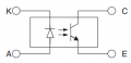
Previous sensor:

The replace sensor:

The previous sensor has a test circuit made as:
sensor A (Anode) as pin#1, K (Cathode) & E (Emitter) as pin #2, C (Collector) as pin #3.
Connect a 12Vdc PSU return (-) to pin #3;
Connect 12Vdc PSU (+) to one end of 1k resistor and other end to pin #1;
Connect a LED (+) to +5Vdc and other end to pin #2.
Will power on and sensor is not blocked, the LED should turn on. When sensor is blocked the led should be off.
I think if the circuit is correct, this should work on both sensors. But I am not seeing LED on and Off. Any idea of what is happening here?
I have a project and going to replace a Phototransistor. The previous circuit is using a sensor has photo Darlington and the replace sensor just a common phototransistor
Previous sensor:
The replace sensor:
The previous sensor has a test circuit made as:
sensor A (Anode) as pin#1, K (Cathode) & E (Emitter) as pin #2, C (Collector) as pin #3.
Connect a 12Vdc PSU return (-) to pin #3;
Connect 12Vdc PSU (+) to one end of 1k resistor and other end to pin #1;
Connect a LED (+) to +5Vdc and other end to pin #2.
Will power on and sensor is not blocked, the LED should turn on. When sensor is blocked the led should be off.
I think if the circuit is correct, this should work on both sensors. But I am not seeing LED on and Off. Any idea of what is happening here?
Attachments
-
 5.8 KB Views: 2


