So surely this doesn't require a 100 wires? Let me be clear, we are talking about for inputs and the 7 (8 including the display's decimal point) outputs?
This strikes me as a small problem.
The old Texas Instruments TTL manual often had simplified schematics of many devices, I wonder if their binary to 7-seg has that, you could just take a look to get a feel for the scale of the likely solution.
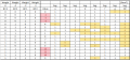
before diving in, create table of values. this will be indispensable for creation of logic.
driving common cathode displays means anode has to be positive so output value "1" will turn that segment on.
table below is that starting point. i took liberty to make DP show the "external error LED".
notice that in this code, decimal values are not matching usual 8421 order.
now you can dive in and create function for each segment... and optimize it using Karnaugh map, DeMorgan's and don't care states. have fun....
I hate the way you're being taught that A is always the MSB. That means that sometimes it's 8 and sometimes it isn't. The way I learned is that A is always the LSB. AFAIK, all of the manufactures of chips at that time also used A as the LSB (if they used A).
Yes, I tried it on Falstad, and it worked perfectly, but due to a lot of wires and connections, it became very complicated when applying it, so I just wanted to knowif there is any way to make the circuit simpler.
these are the boolean functions i reached:
Could you post your truth table so we can see how you interpreted the negative numbers (which don't make sense because you only have a single LED digit).
Although the negative numbers appear 4 times in the problem description, I still question their validity. The person who wrote the problem description also misspelled quadruple as quadrable. That person gets an 'F' for effort...
The DIP switch also doesn't make sense. If the inputs can be 1 or 0, an SPST switch can't accomplish that without resistors to pull the inputs up or down.
The DIP switch also doesn't make sense. If the inputs can be 1 or 0, an SPST switch can't accomplish that without resistors to pull the inputs up or down.
the problem describes using 7400 ICs and those are always TTL. so connecting switches to inputs and GND allows state control. the thing with TTL is that floating input is in state "1".
The DIP switch also doesn't make sense. If the inputs can be 1 or 0, an SPST switch can't accomplish that without resistors to pull the inputs up or down.
This further supports the assumption that 7400 indicates that it is, indeed, the TTL family. In that family, unconnected inputs are pulled HI internally. It's pretty poor design practice to rely on that without a good reason (which do exist), but seeing poor practice in class labs and assignments is nothing new.
it is a poor practice and i probably should comment more on it, as based on earlier info it looks like lab moved from discrete logic gates to FPGA so students will not manually wire few dozens of TTL ICs and the defaulting to "1" when floating is probably not there or may need to be configured.
My first job was as a technician at HP working on the HP3000 Series III. It was primarily TTL and they never left inputs floating. Noise and leakage can make things unpredictable.

 Facebook
 Google
 GitHub
 Linkedin