Facebook
 Google
 GitHub
 Linkedin
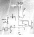
I cannot understand how this circuit works
What is inductor's duty
I am not sure about dual zener mabe it can be a transistor
MOD: Lightened up your image.

What is inductor's duty
I am not sure about dual zener mabe it can be a transistor
MOD: Lightened up your image.
Last edited by a moderator:
 !
!