Facebook
 Google
 GitHub
 Linkedin
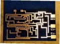
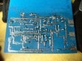
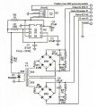
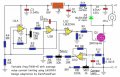
I have a schematic for each of the PWM and EFIE. I also have a circuit board with the parts layout.
What I need is for someone to look them over to see if I got my tracings correct.
Any help is very much appreciated.
Bill
What I need is for someone to look them over to see if I got my tracings correct.
Any help is very much appreciated.
Bill
Attachments
-
 57.8 KB Views: 585
 -
 38.9 KB Views: 617
 -
 132 KB Views: 492
 -
 92.8 KB Views: 1,308