 Facebook
 Google
 GitHub
 Linkedin
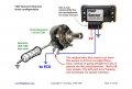
I have 1 O2 sensor before the CAT and 1 after the CAT. The one after the cat has a O2 Sensor fake circuit on it. So I don't have to worry about the one after the CAT.It's a bit premature to whip up a circuit diagram, because I don't know if your vehicle currently has single or dual lambda sensors.
http://www.zzperformance.com/grand_prix/products1.php?id=834&catid=107
This is a link to the O2 emulator.

")


