 Facebook
 Google
 GitHub
 Linkedin
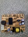
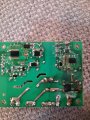
Hi everyone. I was wondering if anyone could identify the components contained in this pcb. (See pic)
Been quoted £3k to have it reverse engineered. But if I can have it made, knowing the exact configuration its pennies.
Thx
Been quoted £3k to have it reverse engineered. But if I can have it made, knowing the exact configuration its pennies.
Thx
Attachments
-
 1.5 MB Views: 53
 -
 1.5 MB Views: 52


