 Facebook
 Google
 GitHub
 Linkedin
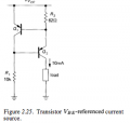
I got two queries...regarding this circuit....
1.Would the voltage across R2 always supposed to be Vbe_Q1 no matter what Vcc is?
2.In order to eliminate early effect in transistor Q2..is it necessary for Vce_Q1 to remain always constant ?
1.Would the voltage across R2 always supposed to be Vbe_Q1 no matter what Vcc is?
2.In order to eliminate early effect in transistor Q2..is it necessary for Vce_Q1 to remain always constant ?
Attachments
-
 21.6 KB Views: 81


