How to wrap a inductor around a resistor on PCB?

prepka

Joined Oct 5, 2020
34
On the contrary - they have soft iron leads.
Please think about what you are saying.even if those leas are iron composition they would not go through the center of the coil to complete the magnetic path. The inductor is fundamentally an air core inductor and are not winding it on the steel leads except to attach the coil wires to the lead ends. The rest of the body materials are non magnetic. I don't think the steel leads make much difference.. BTW, the leads used to be tinned copper in the old days.
 
Last edited:

hrs

Joined Jun 13, 2014
534
the inductor around a resistor is a circuit physical (PCB, point to point, etc...) construction detail, not one designed for special electrical properties.
So it's electrically/electronically equivalent to a resistor in parallel to an air core inductor? If so, why go through this trouble? Is it that wrapping a wire around a resistor is considered a simple way of DIYing an inductor?
 

nsaspook

Joined Aug 27, 2009
16,389
So it's electrically/electronically equivalent to a resistor in parallel to an air core inductor? If so, why go through this trouble? Is it that wrapping a wire around a resistor is considered a simple way of DIYing an inductor?
Yes, for DIY and commercial construction.. It's also a space saver on a PCB, space reduction == cost reduction.

https://www.farnell.com/datasheets/2001459.pdf
REACTIVE LOADING
It is hard for most power amplifiers to drive highly capacitive loads very effectively and normally results in
oscillations or ringing on the square wave response. If the output of the LM3876 is connected directly to a
capacitor with no series resistance, the square wave response will exhibit ringing if the capacitance is greater
than about 0.2 μF. If highly capacitive loads are expected due to long speaker cables, a method commonly
employed to protect amplifiers from low impedances at high frequencies is to couple to the load through a 10Ω
resistor in parallel with a 0.7 μH inductor
. The inductor-resistor combination as shown in Figure 1 isolates the
feedback amplifier from the load by providing high output impedance at high frequencies thus allowing the 10Ω
resistor to decouple the capacitive load and reduce the Q of the series resonant circuit. The LR combination also
provides low output impedance at low frequencies thus shorting out the 10Ω resistor and allowing the amplifier to
drive the series RC load (large capacitive load due to long speaker cables) directly.
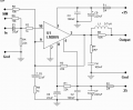
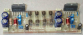
http://www.radanpro.com/Radan2400/Pojacala/Single Chip 50W Stereo Amplifier.htm

1648420849656.png
1648420881868.png
 

Ya’akov

Joined Jan 27, 2019
10,269
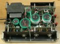
As an aside, I recall my father building a Dynaco “Dynakit” model 400 amplifier and they have you wind the power supply chokes around the filter caps. I found this image of a different model with the same method.

1648457659535.jpeg
 

Ian0

Joined Aug 7, 2020
13,191
I’ve never understood why anyone would want to go to the trouble of winding the inductor around a resistor.
Firstly, if making an inductor with a core, then I would want to know exactly what I’m using for the core.
Secondly, it just makes the whole thing unnecessarily fiddly:
Solder the resistor to the pcb.
Then, wind the air cored choke around some convenient mandrel (I use a piece of broom handle) then solder the choke to the pcb.
Now I use surface mount resistors, so the problem doesn’t arise, and I make the choke out of a spiral pcb track.
 

Ya’akov

Joined Jan 27, 2019
10,269
I’ve never understood why anyone would want to go to the trouble of winding the inductor around a resistor.
Firstly, if making an inductor with a core, then I would want to know exactly what I’m using for the core.
Secondly, it just makes the whole thing unnecessarily fiddly:
Solder the resistor to the pcb.
Then, wind the air cored choke around some convenient mandrel (I use a piece of broom handle) then solder the choke to the pcb.
Now I use surface mount resistors, so the problem doesn’t arise, and I make the choke out of a spiral pcb track.
While spiral tracks do look cool, the only way to make a through hole inductor look cool is to make it look like a boa constrictor attacking a wild pig.
 
Top