Facebook
 Google
 GitHub
 Linkedin
Im trying to make a Star Wars Prop for a course project where the dealine is comming up very fast in days and I need to do the report so really urgent
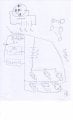
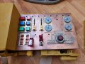
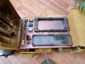
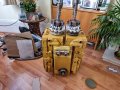
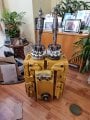
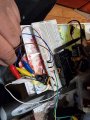
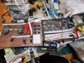
On the prop whihc is a portable control box Dual control box (Left side control panel, a tower in the middle and a right side control panel
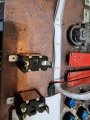
On the the left sider there is a bank of 6 mix ed 12 v and 24 illuminted latching buttons plus 2 illuminatred switches with safety covers
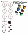
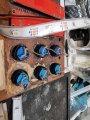
On the right control box there is a set of 6 mixed 24 or 12v non latching illuminated switches,
one on its own, 24 v and a switch or two I think that lights up also 24.v
On control
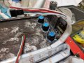
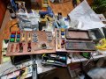
See photos.
The effect Im tryign to get on the left side is like someone launching a helicopter where they press the buttons in quick succession snd they light up and stay lit, likewise the light up switches,
So think the buttins are like engine on fuel pump in life support on etc and the switches are like arm weapon
However the buttons and switches only need to turn on their internal lights. Its just for effect the buttons and switches dont operate anything.
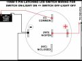
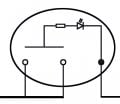
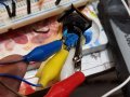
The way this is wired is on each button:
2 pairs
Pair 1 - The Common Prong -----------is connected to the LED Positive Prong----- and the Positive battery pack termial
Pair 2 - The Normally Open NC Prong-- is connected the POSITIVE LED Prong------ on the button and thats connected to ground
on battery pack
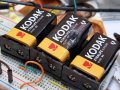
The power supply is 9 PP3 Batteries in series
Whilst I dont need these circuits to do anythgin other than the latched and unlatched illuminated buttons and illuminated switches light themselves up when pressed (Staying on or not depending is latches or not)
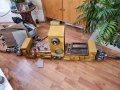
Note in the photos attached I have not fully wired it up Ive just done pairs of wires on the buttons, they mave not been connected in parallel yet or to power and not done anything with the illuminated swtichesyes
I was following this video but presume their set up was intended to switch an in car gadget on and off thus a load and resistance>
Im just trying to fake special effects to look like somone is activiting things of a prop parir of control palentls where the buttoms light up to look cool
from 10 mins on and begging vid showing connections
-
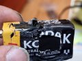
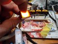
The problem is the batteries heating up and 2 have smoked and had holes blow out of them
I m guessing this is some sort of short circuit issue. Maybe I need some resistor
So thats Panel 2
6 Illuminated buttons that latch in Parrellel
the 12 volts latchign buttons would be like this
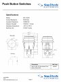
Green Square Latching 16mm Push Button Switch NO/NC 12V
Green latching push button switch featuring a square illuminated actuator and IP65 protection rating. The switch features NO and NC contacts and fits standard 16mm panel cut-outs. The switch is suitable for a wide range of applications including industrial, prototyping, automotive etc. Green 12V...
https://cpc.farnell.com/rjs-electronics/rjs-k16-381-re-65j/illum-push-button-16mm-ltch-sq/dp/SW05393Please advise on what I need to do to get this done and safe Ligthing a load of buttons whtouy over heatign or buttons blowign a hole soiut of them
On the prop whihc is a portable control box Dual control box (Left side control panel, a tower in the middle and a right side control panel
On the the left sider there is a bank of 6 mix ed 12 v and 24 illuminted latching buttons plus 2 illuminatred switches with safety covers
On the right control box there is a set of 6 mixed 24 or 12v non latching illuminated switches,
one on its own, 24 v and a switch or two I think that lights up also 24.v
On control
See photos.
The effect Im tryign to get on the left side is like someone launching a helicopter where they press the buttons in quick succession snd they light up and stay lit, likewise the light up switches,
So think the buttins are like engine on fuel pump in life support on etc and the switches are like arm weapon
However the buttons and switches only need to turn on their internal lights. Its just for effect the buttons and switches dont operate anything.
The way this is wired is on each button:
2 pairs
Pair 1 - The Common Prong -----------is connected to the LED Positive Prong----- and the Positive battery pack termial
Pair 2 - The Normally Open NC Prong-- is connected the POSITIVE LED Prong------ on the button and thats connected to ground
on battery pack
The power supply is 9 PP3 Batteries in series
Whilst I dont need these circuits to do anythgin other than the latched and unlatched illuminated buttons and illuminated switches light themselves up when pressed (Staying on or not depending is latches or not)
Note in the photos attached I have not fully wired it up Ive just done pairs of wires on the buttons, they mave not been connected in parallel yet or to power and not done anything with the illuminated swtichesyes
I was following this video but presume their set up was intended to switch an in car gadget on and off thus a load and resistance>
Im just trying to fake special effects to look like somone is activiting things of a prop parir of control palentls where the buttoms light up to look cool
from 10 mins on and begging vid showing connections
-
The problem is the batteries heating up and 2 have smoked and had holes blow out of them
I m guessing this is some sort of short circuit issue. Maybe I need some resistor
So thats Panel 2
6 Illuminated buttons that latch in Parrellel
the 12 volts latchign buttons would be like this
Green Square Latching 16mm Push Button Switch NO/NC 12V
Green latching push button switch featuring a square illuminated actuator and IP65 protection rating. The switch features NO and NC contacts and fits standard 16mm panel cut-outs. The switch is suitable for a wide range of applications including industrial, prototyping, automotive etc. Green 12V...
https://cpc.farnell.com/rjs-electronics/rjs-k16-381-re-65j/illum-push-button-16mm-ltch-sq/dp/SW05393Please advise on what I need to do to get this done and safe Ligthing a load of buttons whtouy over heatign or buttons blowign a hole soiut of them
Attachments
-
 1.8 MB Views: 6
 -
 1.9 MB Views: 6
 -
 1.3 MB Views: 6
 -
 3.1 MB Views: 6
 -
 1.2 MB Views: 6
 -
 1.4 MB Views: 6
 -
 3.2 MB Views: 6
 -
 3.6 MB Views: 6
 -
 1.8 MB Views: 6
 -
 2.1 MB Views: 6