How to wire a 3 pins IR receiver with NPN/PNP transistor

Thread Starter

Kelvin Lee

Joined Oct 22, 2018
111
Dear Sir/Madam,

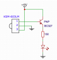
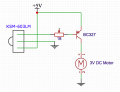
Recently I learn about NPN/PNP transistor, I found a good wiring sample from the Internet. It is very clear to show how a switch should be wired with the NPN/PNP transistor but I have questioned how the wiring should be if I replace the switch with a 3 pins IR receiver? The IR receiver has already contained Vs and GND, when I connect the OUT pin to the base, how about another side like the switch?


Attachments

Last edited:

JohnInTX

Joined Jun 26, 2012
4,787
Here is the full datasheet for your IR receiver (I think)
http://www.vishay.com/docs/82491/tsop382.pdf
Note that the maximum permissible voltage is 5Volts so you couldn’t use it in place of the switch unless you dropped the voltage. If you do that, since the IR receiver’s output is low when receiving a signal, the PNP circuit would be appropriate. Connect he output to R2 in place of the switch. That will turn the PNP on when receiving.

Note that the receiver requires a coded, modulated IR signal to work.

Good luck!
 

Thread Starter

Kelvin Lee

Joined Oct 22, 2018
111
Here is the full datasheet for your IR receiver (I think)
http://www.vishay.com/docs/82491/tsop382.pdf
Note that the maximum permissible voltage is 5Volts so you couldn’t use it in place of the switch unless you dropped the voltage. If you do that, since the IR receiver’s output is low when receiving a signal, the PNP circuit would be appropriate. Connect he output to R2 in place of the switch. That will turn the PNP on when receiving.

Note that the receiver requires a coded, modulated IR signal to work.

Good luck!
Dear JohnInTX,

Thanks for your reply, I get your meaning, so if I can add a resistor between the IR receiver's output and the base of transistor then can drop the voltage, how much voltage I should drop and how much resistance value of resistor I should at, do you mind teaching how to calculate? I know Ohms Law but I don't know how much voltage should be dropped in my case.

Thank you.
 

JohnInTX

Joined Jun 26, 2012
4,787
First things first. If you are going to use a 9V battery for the supply, you need to add a 7805 regulator or similar to drop the voltage to 5V. The TSOP382xx IR receiver is limited to 5V. Do you want to use that IR receiver? Note again that the IR signal must be modulated (switched off and on at 38KHz typical) to operate the receiver.

If you are just looking for a simple IR detector that does not require the modulation (but is more sensitive to stray light), you could use a simple NPN photo-transistor in place of your switch in the PNP circuit.

Which method would you like to use?
 

Thread Starter

Kelvin Lee

Joined Oct 22, 2018
111
First things first. If you are going to use a 9V battery for the supply, you need to add a 7805 regulator or similar to drop the voltage to 5V. The TSOP382xx IR receiver is limited to 5V. Do you want to use that IR receiver? Note again that the IR signal must be modulated (switched off and on at 38KHz typical) to operate the receiver.

If you are just looking for a simple IR detector that does not require the modulation (but is more sensitive to stray light), you could use a simple NPN photo-transistor in place of your switch in the PNP circuit.

Which method would you like to use?
Dear JohnInTX,

Attached please find my final circuit after trying different components, I use the KSM-603LM (http://www.weclonline.com/downloads/pdf/19-02-0603.pdf) and BC327 PNP transistor. I simply get an air-conditioner remote to test it, it works and LED light up.

Next, I want to replace the 150 Ohms resistor and LED by a motor with a fan blade but not work, I test the motor with fan blade, it requires around 800mA to startup and then 24mA to operate.

Any suggestion of which component should be replaced? Hope to make the circuit as simple as it can. P.S. it just a demo, simply press the remote and then turn on the fan, release then off is fine enough.

Best regards,

Kelvin
 

Attachments

eetech00

Joined Jun 8, 2013
3,961
Dear Bordodynov,

Thanks for information, I am not familiar reading the datasheet, do you mind recommend which once is suitable to my case and why?

Best regards,

Kelvin
As Bordodynov has stated, the BC327 PNP transistor is connected wrong. The emitter should connect to VCC and collector to the load (LED).
There should also be a current limiting resistor in series with the base of the BC327.

eT
 

Thread Starter

Kelvin Lee

Joined Oct 22, 2018
111
As Bordodynov has stated, the BC327 PNP transistor is connected wrong. The emitter should connect to VCC and collector to the load (LED).
There should also be a current limiting resistor in series with the base of the BC327.

eT
Dear eT,

I tried to swap the emitter to Vcc and collector to the load, both can light up the LED (of course I remember to swap the LED) but not the motor, I can hear the motor trying to on but I think not enough current to start at the initial stage.

How much of resistance should be used to limit the current in series with the base?
 
Last edited:

eetech00

Joined Jun 8, 2013
3,961
Dear eT,

I tried to swap the emitter to Vcc and collector to the load, both can light up the LED (of course I remember to swap the LED) but not the motor, I can hear the motor trying to on but I think not enough current to start at the initial stage.

How much of resistance should be used to limit the current in series with the base?
What motor?:confused:
You need to post a complete schematic.

eT
 

Bordodynov

Joined May 20, 2015
3,181
I believe that the output current of the low level is so small and an additional resistor in the base will not increase the base current of the transistor.Therefore, I proposed high-gain transistors, but there may not be enough base current for them for an output collector current of 800mA.
Also in the datasheet indicated pulse control, i.e.pulses may be output.To solve all the problems, I propose to use a P-channel transistor and parallel to the gate-source to turn on a capacitor of at least 1 μF.
 

Thread Starter

Kelvin Lee

Joined Oct 22, 2018
111
I believe that the output current of the low level is so small and an additional resistor in the base will not increase the base current of the transistor.Therefore, I proposed high-gain transistors, but there may not be enough base current for them for an output collector current of 800mA.
Also in the datasheet indicated pulse control, i.e.pulses may be output.To solve all the problems, I propose to use a P-channel transistor and parallel to the gate-source to turn on a capacitor of at least 1 μF.
Dear Bordodynov,

Do you mind drawing the circuit diagram so that I can follow how I connect the components?
 

Bordodynov

Joined May 20, 2015
3,181
Dear Bordodynov,

Thanks a lot but your information is too technical and I don't understand. Is there any simple circuit that I can demo the IR can trigger the fan on/off?
You have not clearly defined your goal. This allows us to interpret it in different ways. If you want the engine to work only when you hold down the button of the remote control. Then you can use my scheme. If you want to briefly press the button and the engine is running until you press the button again, then a more complex scheme is needed. The most difficult scheme when using coded information.
 

Thread Starter

Kelvin Lee

Joined Oct 22, 2018
111
You have not clearly defined your goal. This allows us to interpret it in different ways. If you want the engine to work only when you hold down the button of the remote control. Then you can use my scheme. If you want to briefly press the button and the engine is running until you press the button again, then a more complex scheme is needed. The most difficult scheme when using coded information.
I want to press the remote control button, then it turns on the fan, when release then it stop.

I watch this
but I want to turn on a motor fan instead of a LED.
 
Top