Hello Everyone,
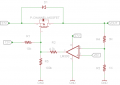
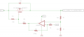
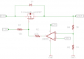
I am using a pchannel mosfet to control an output voltage as the attached. I am trying to understand how to turn off the gate by giving it higher voltage than the source?
the mosfet source voltage is 27v (output of a prior boost circuit from a 12v battery), the gate is constant =12v to be constant on.
So to turn it off, the only idea I thought of is to give the gate the same source voltage of 27v via the lm393 but the issue is that the comparator "eats" appx 1.5v so it might not defently work always (27v-1.5v=25.5v) as the fet gate threshold is from -1.2v (25.5v-27v=-1.5v = will turn it on again).
The mosfet used is IPP80P04P4L-08 and max vgs=+-16v.
Please advice how it can be solved? by using these voltages? or adding another component (prefer not to add)?
Thanks,
Barg
Attachments
-
 5.5 KB Views: 81