How to use limit switches in a project circuit?

shortbus

Joined Sep 30, 2009
10,049
It is better to have tried and failed, than never tried at all.
I take no joy out of buying stuff, it is the journey that is way more important...
I agree with you on that . But there comes a time and place where safety and the chance of breaking the machine you do have comes into play.

If I HAD to do this(make the bend die) I probably would not make it out of one very thick piece of steel. By making it from 2 plates half as thick then joining them together when done. doing it like that would only mean machining a radius on the face of each part, not coming in from the outer edge like machining a "U" shape, it would be machining 2 "J" shapes. And these 2 parts would be bolted to a faceplate and not held in a chuck.

Anyway, have a Merry Christmas!
 

Thread Starter

fiftyv8

Joined Jan 29, 2018
223
Still taking small steps and confidence building since it is all new to me working in the big pond.
I am using slow gears and pressed the shaft into my drop out and it was a really sweet fit.

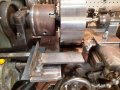
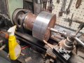
I've set it up and other than the rough laser cut, I was pretty close to center and have now gotten a decent machined surface to the perimeter.
20211221_210143.jpgThat laser start cut was a bit annoying to start with but now is fine.
Next, I will face the side opposite to the chuck and then contemplate the mounting and making of my concave radius cutter gizmo...

Its been a little too hot for the shop over Christmas with 2 days straight of around 44 degrees C where I am and still more heat to come...

Stay tuned.
 

Thread Starter

fiftyv8

Joined Jan 29, 2018
223
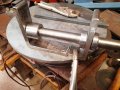
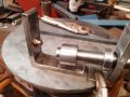
I've scrouged up some scrap metal from my stash and have started making the parts for my radius cutter gizmo.
Pictured is what I have to date.
I am running with what I have, so no ball bearing, just an acorn nut will have to suffice...

It has also been quite hot where I reside, we are talking temps in the 40C degrees range.20211228_091905.jpg20211228_091924.jpg
 

Thread Starter

fiftyv8

Joined Jan 29, 2018
223
Here is the YouTube link that inspired me to make a radius cutter.
The language is Greek as far as I can tell, but it is really self explanatory I think.


shortbus

Joined Sep 30, 2009
10,049
That will work in most cases. But also look at his cutting set up. The radius cutter is inline with the cross feed, so there isn't a cantilevered force on it. In your instance you can't get you cross feed under the work. So I would be very care full when cutting. Your approaching dangerous territory. Hope you don't break yourself or the lathe.
 

shortbus

Joined Sep 30, 2009
10,049
Unless you can get the cross feed under the part, you can't, you will still be cantilevered. The center of the cut away from the center of support. That puts a lot of strain on the tool and the lathe saddle. Don't you have a buddy with a bigger lathe? I think you mentioned that earlier.

Or what if you take off the cross feed cover casting? That is just to keep chips from the feed screw. Sometimes you can gain a little more clearance by doing that, letting you get more inline with your cut.
 

Thread Starter

fiftyv8

Joined Jan 29, 2018
223
Shortbus, I will see my buddy tonight as he will visit me here at home and I can show him my current situation.
Although his lathe is physically larger, when we did a rough check measure previously,we found little to no advantage with his machine other than horse power and more modern controls.

I believe that I may still be able to support my tool holder in somewhat of an unorthodox way, but just need to figure it out a little more first to see if it is do-able.

My main interest is knowing what height my cutter tip should be with respect to the center line of the lathe. Whether it needs to be above or below the center line would be a big help before I set in the rotating cutter holder that I showed in my pic's...
 

shortbus

Joined Sep 30, 2009
10,049
My main interest is knowing what height my cutter tip should be with respect to the center line of the lathe. Whether it needs to be above or below the center line would be a big help before I set in the rotating cutter holder that I showed in my pic's...
The cutter tip, cutting point, should be at or slightly(0.015 or less) below center. On any cutter. By doing this you can have more "meat"/tool to support the cutting edge. If your above center you have to use more of a clearance angle to keep from rubbing and more angle means less tool to absorb the heat which causes faster dulling of the tool.
 

Thread Starter

fiftyv8

Joined Jan 29, 2018
223
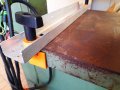
I am not sure how successful this will be, but without this or similar, I will not be able to machine the concave radius curve that is required to make my tube form.

It is just made from scrap and consists of a piece of 10mm thick 90mm wide flat bar bolted/clamped to my lathe bed, which I am hoping will be capable of supporting another piece of flat bar as a bridge between it and my tool post carriage.

The bridge will provide the support platform to carry my radius cutter gizmo once finished.
The bridge has an alignment guide against the large flatbar and seems to be happy to slide in and out as required.
It appears user friendly in training, but under fire I am not sure yet how it will react!!! 20220101_110656.jpg
 

shortbus

Joined Sep 30, 2009
10,049
Yet again you have the cantilever problem. If I had to choose between the plate set up and the regular lathe cross feed, it would be the cross feed.

If going the plate route, why not put an angle iron "way"(don't know what else to call it) on each side of the plate with a cutter assembly in the middle? That would do away with the cantilever problem and direct the cutting forces straight into the lathe bed, like most cutting operations do.

When shown from the view of the last photo I have another hint. When doing a heavy cutting operation like this on a mandrel(your shaft) it's always good to have a driving point on the work. A simple tapped hole with a bolt in the part, then the bolt against one of the chuck jaws. If the part spins on the shaft it could galled making it hard to get the shaft out.
 

Thread Starter

fiftyv8

Joined Jan 29, 2018
223
Shortbus, now that my friend is a very good idea.
Boy I love taking that lump of sheel out of the chuck and then putting it back again, but in this case it will be for good reason.
 

shortbus

Joined Sep 30, 2009
10,049
Shortbus, now that my friend is a very good idea.
Guess how I learned that? :) I 'm just glad some of my hard learned information will help you. Where I served my apprenticeship we did so many things with old worn and some times undersized equipment, that other small mom and pop shops wouldn't even try to do.
 

Thread Starter

fiftyv8

Joined Jan 29, 2018
223
Sorry, I've been off the radar for sometime as I hurt my shoulder which has limited my progress.
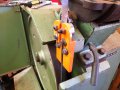
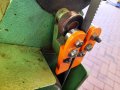
Anyway, I have managed to make a under table roller bearing guide.
My version really only adds the side bearings and I have stuck with the original configuration of the back of blade bearing at 90 degrees to the blade.
Lack of space was the problem for the back bearing modification.
However if somebody set their mind to it, I am sure it would be possible, just a lot more work involved...
 

Attachments

shortbus

Joined Sep 30, 2009
10,049
The back bearing is typical of most band saw guides. I can't see why(just my point of view) you went with ball bearings for the guide though. You said the original guides would put too much heat into the blade, but I have to disagree. The two big names in contour band saws, Doall and Grob both use metal, not bearings for their guides, over the years. And stop to think, the actual cutting of the metal is going to put much, much more heat into the blade than the guides will. Also the bottom guide acts as a type of heat sink to remove the generated heat of cutting.
 

shortbus

Joined Sep 30, 2009
10,049
What is done now, is done.
Time to keep moving forward...
Sorry you feel like that. This is the only place and yours is the only thread here that I get to discuss metal work and machine design, now that I've been retired for so long.

I just know from my experience that that type of ball bearing guide doesn't make it easy to cut shapes/contours in steel or any metal. The blade seems to go wher it wants not where you want it to with those guides. Because of the fact there is only a very small, minimal contact between the bearing and the blade. When I say small it's in the 0.001" range. My 18" saw came with them and couldn't get rid of them fast enough.
 
Last edited:

Thread Starter

fiftyv8

Joined Jan 29, 2018
223
No problem. if I dont like what it does, it can be converted back to original quite easily, but I am sure it wont wander now like it use to but I am not really blaming the guides, my seized tensioner was probably the culprit in that regard. I mainly require straight cuts or ones with very little curve.
Just keeping you on your toes my friend...
 

Thread Starter

fiftyv8

Joined Jan 29, 2018
223
Done with my bandsaw now.
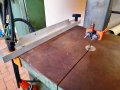
Adapted an old saw table guide I found in a scrap bin which will work for my needs.
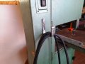
Then added a cable hook as I now have an extra long power lead on my bandsaw so it can easily reach the dedicated power outlet which ensures the blkade runs in the correct rotation since it is a 3 phase motored saw.
So back to the main game real soon...
 

Attachments

shortbus

Joined Sep 30, 2009
10,049
Hope the guides work like you think they will.

But all of this talk about bandd saw guides leads me to fixing my 7"x12" horizontal cutoff saw. It has single ball bearing guides like you made, and it will not cut a square cut no matter what I do or the brand ofblade I buy. So knowing what I do about these type of guides, from experience with my vertical saw, I designed a new set of guides. They will use 4 sets of ball bearings, in pairs, about 1 1/2" apart. Doing it that way should keep the blade from being able to twist in the guides, keeping the cut from leading off. There are 2 bearings stacked on each guide since this is a 3/4" blade.
 
Top