How to trigger a GSM auto dialer

Thread Starter

Simon1969

Joined Sep 14, 2017
3
Hi all,
First post on here.
I have bought a GSM auto dialer https://gsm-activate.co.uk/product/gsm-autodialer/
I am having a small problem triggering the device.
I want to trigger the dialer when there is a loss of voltage.
Basically this is for a farmer who has uninvited visitors in one of his fields.
There is a cable running through the gate which can be connected to a 12v Car battery,
When the gate is opened, the cable coming from the gate drops from 12v to nothing.
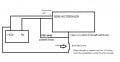
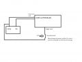
I have drawn a circuit that shows the problem.
I spoke to tech support, and he said that loss of 12v wouldn't be enough to trigger, I would need to change from 12v to 0v.
Any help would be gratefully received.

Thanks

Simon.circuit.jpg
 

ericgibbs

Joined Jan 29, 2010
21,436
hi Simon,
Is it possible to fit a change over switch at the Gate.?
A general purpose micro-switch has change over contacts.
E
 

Reloadron

Joined Jan 15, 2015
7,882
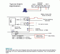
Looking at the GSM AUTO DIALER MANUAL. They do mention 2 inputs: Negative or Positive Triggered but I believe what they are getting at is triggering can be done by either completing a circuit to a positive voltage source or completing a circuit to ground. Either of the two trigger inputs close an internal relay for the trigger process, either Input 1: SMS Text Alert Max 3 numbers or Input 2: Dial Out Call Alert Max 3 numbers and the input must be held high, closing the internal relay for at least 4 Seconds. Looking at the drawing on Page 8 of the manual I would use a SPDT micro switch as Eric suggested. You want a SPDT micro switch and wire it using Common and the NC terminals of the switch as with the gate closed the NC terminals will be open and close activating the unit when the gate is open. You can easily trigger Input 1, Input 2 or both. Additionally since the Inputs drive relays I would not want them active all of the time using power on a battery operated system.

A simple Google of lever operated micro switch will give you hundreds to choose from.

Ron
 

Thread Starter

Simon1969

Joined Sep 14, 2017
3
Hi, Thanks for the replies.

I should have been more specific.
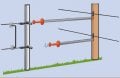
The gate is like the picture here.gate-diagram-2.jpg
Except that there is only one across the opening, not the two as seen in the picture
There is no physical gate, just the sprung cable.
A micro switch wont work.

Thanks

Simon.
 

Thread Starter

Simon1969

Joined Sep 14, 2017
3
Hi,

Yes, the metal hook is making the continuity. So when an unwanted visitor unhooks the hook, to gain access, continuity is lost, and hopefully the autodialler is triggered.

If I use the circuit That DNA has modified, which input on the auto dialer do I connect that wire to on INPUT 1. + or -.

Thanks again for all your help.

Simon.
 

ericgibbs

Joined Jan 29, 2010
21,436
hi Simon,
If you tried the 10K pull down resistor, it would be a LOW going signal [ ie: loss of the +12v from the fence], so I would say the -INP.

However reading that PDF, it will probably not work.?
To check the method:
I would get the GSM unit on the bench, apply +12V to the -INP [ with the 10K to 0V] and then disconnect the +12V to the -INP, this would simulate a gate opening and the GSM should make a Call!.

Lets know what you find.?
E
 

Reloadron

Joined Jan 15, 2015
7,882
Just using a hook I have my doubts about. The connection is really not a definite purpose. The unit works, as mentioned with an internal relay closure for a given period of time. A transistor switch could maybe be added but depending on just a metal chain and hook just does not seem reliable to me.

Ron
 
Top