Facebook
 Google
 GitHub
 Linkedin
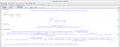
Given the attached schema I'd love to find the analytical temporal and frequency expressions for the current in the 2 branches: i1 and i2.
R0, R1, R2, C1, C2 and Vg(t) are given.
In the time domain can you show me how to set the system of differential equations that will bring me to the solution? Once I have the system it shouldn't be a problem to solve it using for instance odeint in Python.
Thank you in advance!
R0, R1, R2, C1, C2 and Vg(t) are given.
In the time domain can you show me how to set the system of differential equations that will bring me to the solution? Once I have the system it shouldn't be a problem to solve it using for instance odeint in Python.
Thank you in advance!