how to solve and understand this opamp config

Thread Starter

haseebzaib

Joined Jun 29, 2021
8
Hello guys
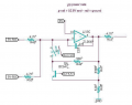
Here I have this portion of the circuit which I cant really understand what it is doing and I want to solve it, so I can understand it. The inverting input is having a 2 signals and there peak is 5V, while on this inverting input we have this transistor with analog switch,this analog switch is being switched by a delay signal whose on time is 50us, this is the portion I am confused in. So I want tips/suggestions to how to understand this circuit and how to solve it, So I could understand why they used this transistor and switch part in this circuit. The value of capacitor is 100nf.

opamp rail voltages 10.6V and ground
3rd stage understanding.JPG
 

Audioguru again

Joined Oct 21, 2019
6,688
Your schematic is a negative image of faint lines on a black background and impossible to see. I changed it to a normal positive image.

Before the analog switch activates, the opamp has no negative feedback so its input voltages cause its output to as high as it can go (8.5V?).
When the analog switch activates then its transistor conducts and reduces the -input voltage and the opamp remains with its output as high as it can go. Nothing happens.
 

Attachments

Thread Starter

haseebzaib

Joined Jun 29, 2021
8
Your schematic is a negative image of faint lines on a black background and impossible to see. I changed it to a normal positive image.

Before the analog switch activates, the opamp has no negative feedback so its input voltages cause its output to as high as it can go (8.5V?).
When the analog switch activates then its transistor conducts and reduces the -input voltage and the opamp remains with its output as high as it can go. Nothing happens.
can u elaborate little more ?
 

Thread Starter

haseebzaib

Joined Jun 29, 2021
8
Your schematic is a negative image of faint lines on a black background and impossible to see. I changed it to a normal positive image.

Before the analog switch activates, the opamp has no negative feedback so its input voltages cause its output to as high as it can go (8.5V?).
When the analog switch activates then its transistor conducts and reduces the -input voltage and the opamp remains with its output as high as it can go. Nothing happens.
if even when the switch closes and nothing happens to output then what is its purpose ?
 

Thread Starter

haseebzaib

Joined Jun 29, 2021
8
Your schematic is a negative image of faint lines on a black background and impossible to see. I changed it to a normal positive image.

Before the analog switch activates, the opamp has no negative feedback so its input voltages cause its output to as high as it can go (8.5V?).
When the analog switch activates then its transistor conducts and reduces the -input voltage and the opamp remains with its output as high as it can go. Nothing happens.
and how did u calculate the output voltage to be 8.5v?
 

michael8

Joined Jan 11, 2015
414
What is the circuit fragment from? Likely it isn't a "steady state" type of circuit, the tl064 is 3.4V/uS so the 470pF capacitor provides the feedback. At 5 Volts in via 4.7K that's about 1 mA. So the capacitor could charge at 1 mA for about 2 to 3 uS before reaching 5V (about all the room from virtual zero (6V) to the supply).

Without knowing what the inputs mean or what the output does, it's all guesses...
 

Audioguru again

Joined Oct 21, 2019
6,688
The minimum, typical and maximum output voltage of an opamp is shown on its datasheet. The voltage range is large then you must guess or measure if your opamp has minimum, typical or maximum specs.
 
Top