How to shift analog signal to different ground

nicsky

Joined Aug 1, 2009
11
I designed this muscle amplifier that runs on +/-5V. I'm powering this with a standard 3.7V lipo stepped up to 10V and then using a potential divider to split the power into 2 rails (+5V and -5V). However, I then want to pass this signal into an Arduino powered by the whole 10V and am wondering how I would go about doing this as the muscle signal is rectified to be completely positive but is technically oscillating between 10V and 5V in reference to the ground being used on the Arduino. I don't know if this is hard to imagine so I've drawn out the basic diagram:


The signal would be going into one of the analog pins on the Arduino to be read by a script but at the moment it would fry the Arduino as it's over 5V, how would I go about translating the signal down by 5V so that it can be safely read by an Arduino while still powering the whole thing off a single battery? I hope this makes sense

Thanks in advance
You can use a differential amp, instrumentation amp or full differential opamp like lt1992. I have done similar for the same reasons You could use opamp with 0v and 5v and ac couple signal. The emg signal doesnt need dc and you can save a rectifier by using a op amp that only outputs pos signals
 

Thread Starter

Rossosaurus

Joined Aug 23, 2019
24
Yeah but understand grandparents appreciate things like that and keep in mind we are not going to be here forever. :) We also tend to be proud of our grand kids and brag on you all the time.
Oh I have absolutely no issue working on cars. It's actually one of my hobbies.

A simple level shifter would handle this no problem. It's a simple circuit, simple analysis, no mosfet required just an op amp. It can be made high precision if needed too.
I might still use a voltage shifter I haven't decided yet but I don't like not understanding things and I wanted to understand how the circuit @crutschow put together for me works.

No, the R6 current is not constant, as its equal to IM1d.
All the -5V does is offset the voltage.
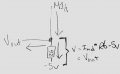
The R6 voltage is thus IM1d * R6 - 5V
Ok, so the current flow is like this?:2020_03_15 13_33 Office Lens(1).jpg

Vout is equal to the voltage dropped over R6 which is equal to the voltage needed for the current of M1d to pass through R6 - 5V? Which equals IM1d * R6 -5V like you say. If I've got this right that means I've finally understood this concept and it's only taken me an entire month to get to grips with it.
 

crutschow

Joined Mar 14, 2008
38,573
I've got this right that means I've finally understood this concept and it's only taken me an entire month to get to grips with it.
Yes, you have it right.
It's a somewhat unusual circuit, which can take awhile to fully understand its operation.

The circuit voltage gain is determined by the value of R6, as MrAl noted, so obviously any input load resistance of the circuit looking at the signal must be included in parallel with R6.
If necessary, the value of R6 can be increased so that the parallel value of the two is equal to the unloaded value of R6 (20kΩ).
The input impedance of an Arduino is quite high so, if that's the only load for the circuit, there should be no need for any adjustment of R6's value.
 
Last edited:
Top