How to select a mosfet driver(opto..) for 24v to 12v buck converter

Thread Starter

meshcurrent

Joined May 28, 2022
26
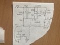
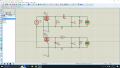
I want to create a 24v to 12v buck converter. I am trying to control mosfet with optocouplör. I have 25kHz-50kHz pwm signal from arduino/pic16f877A. I have some mosfets like IRFZ44N, IRF540N IRF4905 and etc. I am using PC817 opto but I guess it is not suitable for high frequency pwm like 25kHz. Because there are some pwm problems on rise and fall times. I have found 6n137 opto but it does not works on 5v vcc. I need to drive mosfet like 10v-15v. What should I do. If it is possible, how can I delete the rise and fall time on pwm output from opto. My English is not very good. Sorry for all wrongs on text and thanks for answers.
 

Thread Starter

meshcurrent

Joined May 28, 2022
26
Thanks for your answer. But I don't understand something about your circuit. Why are you using 2n3904 and 12v zener diode. Is it possible to use mosfet which I have(n channel). And are you sure pc817 is sufficient for my buck converter. At the some time I want to tell you about my all circuit. My all circuit should do 24v to 12v and -5 volt. Thanks for answer again.
 
For using N-ch in high-side you need a bootstrap driver since to switch N-ch a high voltage is needed ( higher than 24V). With P-ch it’s easier.

A zener doesn’t allow the voltage betwee G and S to be higher than 12V. A 24V would destroy the gate.

A 3904 bjt discharges the gate of mosfet much faster than just some pull-down resistor.

Btw, there is a version of buck with switch on low-side. There you can just simply use a N-ch.

1716133192988.png
 

Thread Starter

meshcurrent

Joined May 28, 2022
26
I have a circuit like this. is it false. it does not work properly I should get -5v and 12v output. If it is false What are the wrongs. Please help me about this topic. I really struggle with this for 1.5 months
 

Attachments

LowQCab

Joined Nov 6, 2012
4,356
It's never a good plan to limit yourself to whatever Components that You have in your "Junk-Drawer".

Each individual Component must be carefully selected for the exact job it is expected to perform.

How much Current do You need at ~12-Volts ?
.
.
.
 
For 24V to 12V buck you should set the Duty about 50% (I neglected diode drop) according formula for continous conduction mode:

D=Vout/Vin=12V/24V= 50%

Similar, find the formula for inverted buck-boost in some book and calculate duty needed.

Btw, your generator should be connected between G a S (positive to Source and negative to Gate).
 

Thread Starter

meshcurrent

Joined May 28, 2022
26
It's never a good plan to limit yourself to whatever Components that You have in your "Junk-Drawer".

Each individual Component must be carefully selected for the exact job it is expected to perform.

How much Current do You need at ~12-Volts ?
.
.
.
I am free to select the current but I need 0.5 or 1A at 12v
 

Thread Starter

meshcurrent

Joined May 28, 2022
26
For 24V to 12V buck you should set the Duty about 50% (I neglected diode drop) according formula for continous conduction mode:

D=Vout/Vin=12V/24V= 50%

Similar, find the formula for inverted buck-boost in some book and calculate duty needed.

Btw, your generator should be connected between G a S (positive to Source and negative to Gate).
I understand caltulations on this circuits about duty cycle. I know %50 duty cycle to 24v to 12v. But 20.80v was for 24to -5v. Bu I have forget to use buck-bust duty formula. I will look is thanks.

I don't understand this message on your repy. My curcuit is wrong in connection of vsource?
"Btw, your generator should be connected between G a S (positive to Source and negative to Gate)."

Thanks for answer.
 

ericgibbs

Joined Jan 29, 2010
19,191
Hi meshcurrent,

I raised the query after reading your:
Thanks for the answer but I must use mosfets for my buck converter.

May I ask why you must use MOSFET's?

E
 
Top