In some parts of the world, in some groups, they will steal dirty socks and your half eaten candy bar. Most of us have not seen that part of the world. For which they should certainly be grateful!!
In some parts of the world, in some groups, they will steal dirty socks and your half eaten candy bar. Most of us have not seen that part of the world. For which they should certainly be grateful!!
BTW in all three schematics (post #1) the text says that the Q3 collector current is 500 mA. It is not. With a 12 V battery and a 1 K resistor, the maximum collector current "for Gate Drive" is 12 mA.
AND - If you change the shift register to a 4000 series CMOS part, you can eliminate the 5 V regulator circuit and run the entire circuit on 12 V battery power directly.
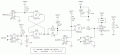
Working through the second schematic in post #1, I think I have part of it figured out.
When power is first applied, U1 (555) starts oscillating immediately. There are no control signals to the 555, so it runs continuously no matter what else happens in the circuit.
The 555 output clocks the shift register (164) through D3. This clock signal is diode-OR-ed with the Q7 output of the 164. If the "ManualV" switch is off, 164's data inputs are held low by R10 and the circuit constantly clocks a 0 into the 164. Because of this, all 8 shift register outputs remain 0's. The Q7 output never goes high and the 164 is clocked continuously.
When ManualV is switched on, 12 V from the battery is attenuated and applied to the 164's data inputs. Because ManualV can be activated randomly within a clock period, it must be switched on for a minimum of one 555 clock cycle to assure that at least one "1" is clocked into the shift register. 8 clock pulses later, Q7 goes high and clamps the clock input high through D4. These 8 clock pulses are the 40 second delay. The timer circuit freezes with Q7 high. To restart the circuit, a signal is applied to optocoupler U3. This resets the 164, driving its Q7 output low, releasing the clamp on the clock input, and allows the 555 to drive the shift register again.
All of that amounts to a latch with a 40-second delayed set and an instant reset.
The 2nd half of the circuit, everything to the right of U2, is independent of this timer. There is no feedback from the other two control inputs or the circuit output. Only optocoupler U3 or cycling the 5 V power can reset the shift register and restart the timer.
The right half of the circuit is the output power switch MOSFET with three control inputs. One is the output signal from the timer, one is a local switch to override the timer and force the output to turn on, and one is an optocoupler for an external signal to force the output off. The OFF control has priority over the ON control, and both have priority over the timer output. If both signals are active, the output remains off.
In some parts of the world, in some groups, they will steal dirty socks and your half eaten candy bar. Most of us have not seen that part of the world. For which they should certainly be grateful!!
I lived in that part of the world in my youth. I've seen criminals bash the head of some poor guy in with a rock for a stick of mystery meat, nobody on the streets has or ever will have EMP weapons and the local law enforcement has guns they love to use.
You're right, today that and a lot worse is happening on the streets in America because of drug abuse.
"n", Thank You for verifying what I mentioned. So I see that the TS has an issue in protecting personal property.
BUT unless that "steel enclosure" is made of tougher stuff, it can be opened by somebody no stronger than me, using a K-Bar or some similar military knife and a serious hit. Just a scaled up version of opening a steel coffee can with a "pen knife." OK, not everybody's "pen knife."
So it seems that the system is rather complex, and no clue as to how it can be produce.
BUT I certainly do not know the resources available to "Parmeet Ghai", and I will not try to guess.
It still seems to me that the motorized timer scheme will be more immune than an electronics package. I have seen those devices with a spring reset option, so the only challenge will be a DC motor to turn it.
ChatGPT is a useless source for this sort of information. It's just repeating paranoid fantasies about EMP attacks and weapons. This is how you open a high security door.
No need for EMP, just a couple of jumper clips and a power supply.
I do understand the need for security. A simple mechanical safe combination lockbox is a lot simpler and is also EMP proof. Most electronic lock designs are defeated on the mechanical side because that's what really keeps the lock, locked.
I do understand that mechanical part of the lock is the one that can get compromised first. I mean there is a device called "jaws of life" which is a hydraulic cutter that can cut through car doors like butter.
I was hoping for some electrical engineer with years of experience to may be provide some pointers about keeping the electronics safe against those kind of attacks but still your point of view is well noted and appreciated. Thank you . cheers
There are, and have been for many long years, locks that snap closed and locked when a door is shut, totally independent of any external action. Some of those locks are adequately immune to external manipulation.
In addition, there are electrical and electronic combination locks that provide an alarm signal at any incorrect attempt to unlock.
And another device that is forbidden on this site is the "Black Max" protection system, normally used to secure a motor vehicle against unwanted access. That device has been demonstrated to be effective every time. It IS RATHER LETHAL!
Thanks for getting back to me. I need to avoid mechanical keys, passwords etc. entering a lock combination cannot be safe when its being done in public. you just dont know who is watching you especially with smartphones with high speed cameras with high frame rates and 20x zoom.
You are right about mechanical locks that would close themselves but then they reply on some other key mechanism to open like a car lock. it uses a mechanical key or a wireless signal.
my design allows the lock to be closed on it's own and then also open on its own with a alarm clock as its open signal. I just wanted to safe guard against electronic attacks.
I will look into the "Black max" device. its probably out of my budget . Thanks again.
1. You keep using the word "trigger" and it is not clear what you mean. Is this a on/off power switch, a pushbutton switch, an external signal coming through a opto-coupler, or something else? Please explain in physical and electrical detail how the circuit is started.
2. How are you getting a mechanical clock to "trigger" an electronic circuit?
3. Do you mean that the circuit releases the solenoid after the *lid* is opened? If so, how does the circuit sense that the lid is open?
4. What is the power source for the system? Where is it located? ALSO - what state should the system be in when power is interrupted and then re-applied? Still waiting for a timing diagram that shows how the system states and control signal states interact.
5.
If the circuit can be controlled by an external electric signal, what is this signal and where does this signal come from?
I appreciate you looking into the detailed working of the circuit. This is truly helpful. I will explain the basics here. I was hoping that some electrical engineer would look at the LTSpice schematics (.asc) files that I have uploaded on my google drive (link in the original post) and then just have the circuit reviewed and give out pointers on how to keep it safe against the attacks that I have listed but let me still give out as much details as I can here.
1) manual trigger is mechanical contact between 12V from battery + to R5
alarm trigger is the mechanical contact between regulated 5V + and Diode D5
Reset trigger is the mechanical contact between R15 and a 1.5V+ from a AAA Cell.
override off trigger is the mechanical contact between R18 and a 1.5V+ from a AAA cell.
Circuit has common ground.
2) a mechanical alarm clock has mechanical contacts inside that turn on a "alarm" sound connected to the clock's battery source.
3) the delay caused by the shift register allows me to close the lid and then once the delay has been completed then the circuit closes the lock by using a stepper motor (scotch yoke) and a solenoid.
4) power source is a 12V lithium ion battery placed next to the circuit. its the label in my schematic labelled "battery". The circuit would most probably be in idle state where power is on but shift register has not been "loaded" and alarm trigger has not been raised yet.
5) I believe that a high frequency/ high voltage noise or EMP or something of that nature would cause the electronics to have the mosfet M1 conduct. In an event of a failure, mosfet should remains OFF.
6) I am in India, new Delhi
Thanks
that is a good point. Keeping that lock safe will allow me to get a job and then a home.
it contains all my electronics like a smartphone ( haven't bought one yet), laptop, a keypad phone. these devices keep getting messed with hence the need for a lock. that's all I can explain for now.
1. When the shift register has been clocked 8 times, its operation is frozen with the Q7 output high. This means that MOSFET M1 is turned on *continuously*. With a 12 A load, this will drain the battery quickly.
2. In your schematics you have one side of the load connected to GND, and the p-channel FET pulls the other side up to the battery voltage. Is it possible to reverse this? IOW, nave one side of the load connected to the battery, and have an n-channel FET pull the other side down to GND? This might make the output circuit less complex.
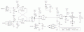
Just for fun, here is a first pass at a simplified design concept. No oscillator, no divider or shifter, just 3/4 of a quad NAND gate package. The operation should be the same as in the post #1 schematics. By using logic gates as circuit elements, three steering diodes and resistors were eliminated. Also, everything runs on battery voltage, eliminating the U5 voltage regulator and its support components.
Key to this design is the use of gates that have Schmitt trigger input stages, This lets them operate with input signals that have very slow rise and fall times, such as an R-C circuit with a 1 minute fall time.
U1A and U1B form the timer control flipflop. C1 assures that the circuit powers up in the "reset" state. In this state, D1 clamps the voltage across C2 to a high voltage near Vbatt.
R2-C2 is the main 40-second timer. Pressing the Manual switch Sets the flipflop. The U1B output (pin 4) goes low, and C2 begins charging "down" through R2. After approx. 40 seconds the lower end of C2 goes below the U1C input threshold.
U1C acts as an inverted-input OR gate - if either input goes low, the output goes high. This turns on Q1 and pulls the lower side of the load to GND. Pressing the Alarm switch pulls pin 8 low and turns on the output. This overrides the timer control signal at pin 9.
As in the original schematic, U4 is an optocoupler for a signal that turns off the output no matter what is going on anywhere else in the circuit. This overrides both the timer and the Alarm input by pulling the Q1 gate to GND, turning it off. In case the U1C output (pin 10) is high, R5 protects the gate's output from a virtual short circuit to GND through U4.
Please review this to see if the operation is correct. I'll add three filter capacitors to protect the gate inputs and Q1 from EMI. Note that some of the part numbers are different from your schematic; these are not recommended changes, I just used similar parts that already are in my design libraries. Click on the schematic for a larger image.
A few words of caution: I have a wonderful tool, a motorized tool that uses a grinding disc at high speed. The cheap one was $20 USD, and it will cut thru quarter inch steel in less than a minute. It can cut thru a hardened steel rod, such as a high quality padlock shackle, in about a minute. So the best passive container/enclosure is not really that very secure.
So an active protection system will be more effective, although it may well be a lethal hazard to those seeking to defeat it. So there are multiple considerations, depending on your specific situation.
Just for fun, here is a first pass at a simplified design concept. No oscillator, no divider or shifter, just 3/4 of a quad NAND gate package. The operation should be the same as in the post #1 schematics. By using logic gates as circuit elements, three steering diodes and resistors were eliminated. Also, everything runs on battery voltage, eliminating the U5 voltage regulator and its support components.
Key to this design is the use of gates that have Schmitt trigger input stages, This lets them operate with input signals that have very slow rise and fall times, such as an R-C circuit with a 1 minute fall time.
U1A and U1B form the timer control flipflop. C1 assures that the circuit powers up in the "reset" state. In this state, D1 clamps the voltage across C2 to a high voltage near Vbatt.
R2-C2 is the main 40-second timer. Pressing the Manual switch Sets the flipflop. The U1B output (pin 4) goes low, and C2 begins charging "down" through R2. After approx. 40 seconds the lower end of C2 goes below the U1C input threshold.
U1C acts as an inverted-input OR gate - if either input goes low, the output goes high. This turns on Q1 and pulls the lower side of the load to GND. Pressing the Alarm switch pulls pin 8 low and turns on the output. This overrides the timer control signal at pin 9.
As in the original schematic, U4 is an optocoupler for a signal that turns off the output no matter what is going on anywhere else in the circuit. This overrides both the timer and the Alarm input by pulling the Q1 gate to GND, turning it off. In case the U1C output (pin 10) is high, R5 protects the gate's output from a virtual short circuit to GND through U4.
Please review this to see if the operation is correct. I'll add three filter capacitors to protect the gate inputs and Q1 from EMI. Note that some of the part numbers are different from your schematic; these are not recommended changes, I just used similar parts that already are in my design libraries. Click on the schematic for a larger image.
Thank you for sticking out for me and offering me these great design ideas. Your proposed design is quite similar to my first design where I used a 555 as latch and had it on by default when system started and then I had a RC for a delay afterwards.
in your circuit, the latch is turned on with a manual trigger (SW-PB) so that makes it more secure and then you have the RC network for delay. This is a great idea. this prevents the latch from being on in its default state when system is powered on.
a nand gate after that allows either alarm or manual trigger to power the n-channel mosfet which is what I need and it has a schmitt trigger which is also what I need.
however I wanted to safeguard high voltage line from the battery because other components running off of it are going to be least protected and vulnerable to attacks. if a battery VCC is connected to a component like that then grounding the other terminal of that component makes it easier for the lock to be opened by someone else. this is why I used a p channel mosfet so the control that is turning on the battery VCC is safe inside its own metal box instead of having the battery VCC outside the metal case with less secure components like a solenoid.
in my final design, I have removed the delay capacitor for the p channel mosfet and have used a strong pull up of 1K. that ways even if the gate driver TC4426 with schmitt trigger is damaged then the p-channel mosfet will be strongly pulled down and remain turned off.
once again, I thank you for your design ideas and recommendations. For now I will proceed further with design3 in my original post and post the results real soon. Thank you for all your help.
I am not sure why you need so much autonomy for the locking action, but it seems that using a limit switch (mechanical or optical) such that closing the lid latches the box (possibly with a warning buzzer and a short delay) is more useful being closed loop as opposed to counting on a timer that has no idea if the box is even closed.
I would also question why a thief wouldn’t just steal the box. I would include a tamper alarm so if the box is moved or otherwise molested after locking it would alert you so you don‘t just sleep through it.
One final thing I would do is to use something like an IMU so I could tap a code on the box and open it if I needed access and it had been locked. Having a phone and a laptop isn’t going to be very useful if then you need them, they are locked in a box you can’t open.
As another member pointed out, this whole thing seems like such overkill that I can’t help but wonder if you are doing it to avoid doing something else, more effective, to improve your situation. There is an undercurrent of exaggerated importance which seems to be driving this. EMP, fuzzing and glitching… why not be concerned about an angle grinder attack?
Good luck, and I hope you can do some introspection and maybe find a different, more effective, area to focus on in your quest to improve your situation—from here, this seems exceedingly unlikely to be a good investment in terms of cost-benefit, or even any utility at all.
Here is a schematic update. This one returns to a p-channel output transistor with a turn-off resistor.
I added three 0,1 uF noise suppression capacitors C5, C6, and C7 to the U1A, C, and D gate inputs. U1B already has one in the power-on-reset capacitor C1. These should harden the circuit against EMP events.
An EMP event has a lot of very high frequency harmonics. Without these additional capacitors, the circuit impedance at each of the inputs is 10 K ohms. At 1 MHz, a 0.1 uF ceramic capacitor has an impedance of only 1.6 ohms. Thus, the amount of induced current needed to cause a false circuit state is increased by a factor of over 6000. The caps should be a high-frequency ceramic type with the shortest possible leads between the input pins and the IC's GND pin.
In all three post #1 schematics, the 555 oscillator period is 10 seconds. At this rate, a 40-second delay should be decoded as 4 clock cycles. However, in all schematics the output is activated after 8 clock cycles. Thus, the actual delay between pressing the manual switch and activating the lock mechanism is 1 minute 20 seconds.
Also, in schematics #2 and #3 it looks like the Manual switch must be pressed/flipped/toggled for a full clock cycle to guarantee that a logic 1 is clocked into the shift register's first stage. This is either 5 or 10 seconds, depending on the intent of the oscillator frequency. The schematic #1 circuit is different, and it is not clear what the Manual input is supposed to do. It looks like it is just a clock output disable, done by grounding the Q2 base.
I am not sure why you need so much autonomy for the locking action, but it seems that using a limit switch (mechanical or optical) such that closing the lid latches the box (possibly with a warning buzzer and a short delay) is more useful being closed loop as opposed to counting on a timer that has no idea if the box is even closed.
I would also question why a thief wouldn’t just steal the box. I would include a tamper alarm so if the box is moved or otherwise molested after locking it would alert you so you don‘t just sleep through it.
One final thing I would do is to use something like an IMU so I could tap a code on the box and open it if I needed access and it had been locked. Having a phone and a laptop isn’t going to be very useful if then you need them, they are locked in a box you can’t open.
As another member pointed out, this whole thing seems like such overkill that I can’t help but wonder if you are doing it to avoid doing something else, more effective, to improve your situation. There is an undercurrent of exaggerated importance which seems to be driving this. EMP, fuzzing and glitching… why not be concerned about an angle grinder attack?
Good luck, and I hope you can do some introspection and maybe find a different, more effective, area to focus on in your quest to improve your situation—from here, this seems exceedingly unlikely to be a good investment in terms of cost-benefit, or even any utility at all.
mechanical locks can be easier to bypass than electro-mechanical locks. for starters, with my design there is no key or passwords that be looked at with some smartphone at a few meters away with 20x zoom settings. its some evident from "mr lock smith" channel on youtube (https://www.youtube.com/channel/UCjokUyTM9hMhTBjqgbuVtCA) that Neodymium magnets can be used to open most lockers. from him I got the idea of placing the lock right at the center of the steel box so its equidistant from top , bottom, left and right sides of the steel container hence minimizing the effects of a strong super magnet.
yes a alarm will be included as well. problem is that I am homeless and this box will keep my belongings safe and hack free. so far all my gadgets have been messed/hacked with. its a long story but the kind of people after me are looking for sabotage rather than out right damage that will evident against other people. this makes getting a job that much difficult while to other people it looks like as if I am not even trying.
no passwords or codes can be used as they can be guessed or "sniffed" out using cameras, thermal vision etc. I have a workaround for that but its in developement stage.
In case of the box getting stuck at close position, I would have to cut out the 4 main bolts holding the lock in place with a hacksaw which could have half a day easily.
I am almost done implementing the lock and will post a video with much more detail. Thanks for helping me out.

 Facebook
 Google
 GitHub
 Linkedin