How to SafeGuard against EMP/High Frequency Attacks, Forced System Reset and Force System Failure

Thread Starter

Parmeet Ghai

Joined Mar 23, 2024
14
How to SafeGuard against EMP/High Frequency Attacks, Forced System Reset and Force System Failure

IMPORTANT: I cannot use a microcontroller because of my living conditions whatever electronic that I own which contain firmware/software is vulnerable to re-programming attacks hence I can only work with hardware. no firmware/software.

I have the following circuit designed for a automated lock application.Can anyone think of conditions where the system can be compromised causing a power P-channel MOSFET to conduct and have a high power solenoid activated and also safe guards against EMP attacks, high frequency attacks, forced system resets and force system failure?

Any help will be greatly appreciated.

Note that the timing delay does not require precision. The circuit will be enclosed in stainless steel container hence offering some shielding. cannot use any micro controllers. Due to my living conditions any electronic gadget with software/firmware is vulnerable to re-programming/hacking hence only hardware can be used.

What is needed from the circuit is the following:
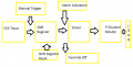
1) Manual trigger to activate the system otherwise the system remains idle.
2) A delay of >40 seconds after the system is activated.
3) After the delay is over then system activating a gate driver for a P-channel MOSFET.
4) P-channel MOSFET activates a high power solenoid for a lock and then gets disabled.
5) The initial trigger should never happen by itself unless manually triggered like in step 1.
6) Later an Alarm signal will trigger the power mosfet against
7) A override OFF signal then turns off the mosfet

Besides the solenoid, a stepper motor is also activated which is connected to a Scotch Yoke. it rotates in only one direction. which is why there is a need to turn on and off the mosfet twice. at 180 degree, it will activate the lock. at 360 degree it will unlock the lock.

The circuit should withstand:
1) Whole system resets.
2) Whole system failure.
3) High frequency/EMP attacks.

Preferred condition under such scenarios is that the P-channel MOSFET remains OFF thus preventing the lock from opening under default/reset/error conditions.

Typical use case:
1) After manual activation a delay of >40 seconds.
2) After the delay is over then gate driver activates P-channel MOSFET activating a high power solenoid lock.
3) The initial trigger turns off via optocoupler turning off the MOSFET.
4) The initial trigger never turns on unless its manually activated like in step 1.
5) A alarm activates the gate driver turning on the MOSFET.
6) The alarm is turned off via optocoupler which turns off the MOSFET.

First design:
It only used a Latch for initial trigger and a capacitor at the base of a NPN driver for delay. Some other design flaw made me consider the effects of a system reset and it turns out that the latch would trigger on by default under reset hence its omitted.
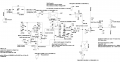
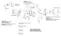
Second design:
The second design involved a 555 timer and a CD4017 (LTspice simulation attached). Everything works great except at system reset, the clock output from 555 shows a jitter which if not handled with a 1 µF capacitor leads to the system being triggered by default at system reset. If capacitor goes bad in case of a EMP attack then system is compromised hence this design was scrapped too.

Third/final design:
This one uses a 555 timer as well and a 74HC164 SIPO shift register replacing CD4017 and TC4429 as gate driver instead of a NPN (2N2222). the 74HC164 has a strong pull down at the input A and B thus requiring at least 9 V to be triggered and TC4429 has a built in Schmitt trigger which prevents noise and jitters. PS:I have used LTC1693-5 from analog.com as replacement for TC4429 because the model was giving out too much of a problem.

I have datasheets, LTspice schematics, LTspice libraries and symbols and screenshots of those schematics attached for reference here:<Mod: deleted link>
 

Attachments

Last edited by a moderator:

Papabravo

Joined Feb 24, 2006
22,058
I fail to see any utility in these designs. Mostly because there is very little way to test any of it unless you have access to a nuclear weapon to generate the required EMP. I don't know enough about the High Frequency Attack to know if there is any utility, but I have my doubts. Maybe some background on the actual problem.
 

Ya’akov

Joined Jan 27, 2019
10,226
Welcome to AAC.

Your post is shrouded in mystery and—no disrespect intended—sounds of unlikely necessity. However, relying on the meager information provided and employing a little mind reading, I would suggest a cam-timer that avoids all solid state components.

1743154018320.jpeg
 

PinkyP22

Joined Mar 28, 2025
1
Your question is big. I really couldn't understand that. The designs you shared are perfect, but the things you mentioned seem difficult to read. Kindly write it in short form so that we can recommend you some things.
 

BobTPH

Joined Jun 5, 2013
11,463
IMPORTANT: I cannot use a microcontroller because of my living conditions whatever electronic that I own which contain firmware/software is vulnerable to re-programming attacks
How so? A microcontroller, unless specifically programmed to do so so, cannot be re-programmed without physical access. And physical access would allow hacking any other mechanism you might come up with.
 

AnalogKid

Joined Aug 1, 2013
12,043
The designs are not perfect. They have several major errors.

The first schematic is almost impossible to read. It has so much text on top of other text that it is useless. The other two are only slightly better. For example, two signals go through resistors to the shift register clock input, but both resistor designators are unreadable. Also, there is no pull-down resistance or device at that clock input, so under some conditions the input is floating. If you are worried about radiated interference, this is the worst possible condition. A floating CMOS input is a great radio receiver.

Why is there feedback from the U2 Q7 output to its own clock input? Why is this signal summed with the 555 output?

Why are there optical couplers in the circuit? Everything has common power and ground, so there is no true isolation.

It looks like M1 is being turned on very slowly, but turned off rapidly. Why? Why is there a high-speed MOSFET driver in front of such a low-speed circuit? Since you are not driving M! with a 100 kHz signal, I don't think U6 is necessary.

Why are there three schematics?

Please expand the one schematic you want to discuss and move the components around so every reference designator, component value, and pin designation is clearly visible. There is plenty of room for this without making the page larger. Remove unnecessary zig-zags so the signal flows are clear. At this point we do not need voltage and current values.

Schematic diagrams are a language, and like all languages there are conventions regarding normal usage. Power should flow from top to bottom. Signals should flow from left to right. And GND symbols *always* point down. Example, M1 and R11 are upside down. U3 is upside down and backwards.

Update. It appears that the 555 and 164 are supposed to combine to produce a signal that is delayed approx. 40 seconds, at which time the 164 inhibits itself from further shifting. If this is the intent, there probably are ways to do this with less clutter. This is a common circuit request, basically for a long-period monostable. One way to do this is to replace both parts with a CD4060. This is an oscillator and counter in one package, and can generate very long delays with a relatively small timing capacitor. This would remove around 7 passive components plus U1 from the circuit. As a guess, I'd say that the value of C3 could be reduced by approx 50x. D6 and R14 can be connected to a lower-order bit so you have a heartbeat LED to indicate that the circuit is actually counting.

Separate from all of that, neither your text description nor the notes embedded in the schematic make any sense about what you want the circuit to do. Please post a timing diagram showing the input and output signals.

ak
 
Last edited:

nsaspook

Joined Aug 27, 2009
16,249
How so? A microcontroller, unless specifically programmed to do so so, cannot be re-programmed without physical access. And physical access would allow hacking any other mechanism you might come up with.
and there are OTP (one time programming) versions of microcontrollers. I can guarantee his circuits are not hack-proof. The best systems are hack-resistant to some attacks but not all.
1743177801521.png 1743177910362.png
 

MisterBill2

Joined Jan 23, 2018
27,159
REally, the motor driven cam timer suggested by "Y" in post #3 will be almost invincible to both EMP of a magnitude that will not burn out the motor, so it should survive all but a cutting torch or nuclear attack.
 

nsaspook

Joined Aug 27, 2009
16,249
REally, the motor driven cam timer suggested by "Y" in post #3 will be almost invincible to both EMP of a magnitude that will not burn out the motor, so it should survive all but a cutting torch or nuclear attack.
Mister hammer will just smash the door or wall in.

1743186584864.png
Locks only stop amateurs. The guy with a shotgun is a lot more likely than a EMP attack.
 

MisterBill2

Joined Jan 23, 2018
27,159
The fact stands that we have not much clue as to the thread starter's situation, nor his location. The reality is that situations vary around the world. An electric fence charger would be a fair deterrent in some areas, while in other areas it would result in nasty visits from the local law enforcement agencies because it could injure a home invader.
 

AnalogKid

Joined Aug 1, 2013
12,043
First pass at a cleanup of one of the schematics. This replaces the 555 and 164 ICs and both optocouplers with a CD4060 and two transistors. Obviously this does not replace the entire schematic. It is a starting point. The remaining functions of the original circuit can be added once they are explained.

When power first is applied, R1-C1 holds the Reset input high for approx. 100 ms. When this releases, the oscillator starts. R4 is there to discharge C1 when power is removed. This shortens the recovery period of the reset circuit.

R2-C2 set the oscillator frequency. After 8192 cycles, the Q14 output goes high. This turns on Q1, which turns on Q2, connecting downstream circuits/devices to the battery.

SW1 instantly resets U1 and restarts the delay period. Q3 resets U1 whenever its control signal is low.

When U1 output Q14 goes high, it inhibits the oscillator by clamping one of the oscillator circuit nodes high. The divider circuit is not reset at this time. Q14 is high, all other outputs are low, and the circuit is frozen. To reset the circuit and restart another delay cycle, either press SW1 or supply a signal to R6.

R8-D2 provide a visual heartbeat to indicate that the delay is in progress.

Click on the schematic for a larger image.

ak
!!Power-Delay-40s-1-c.gif
 
Last edited:

Thread Starter

Parmeet Ghai

Joined Mar 23, 2024
14
First pass at a cleanup of one of the schematics. This replaces the 555 and 164 ICs with a CD4060. Obviously this does not replace the entire schematic. It is a starting point. The remaining functions of the original circuit can be added once they are explained.

When power first is applied, R1-C1 holds the Reset input high for approx. 100 ms. When this releases, the oscillator starts. R5 is there to discharge C1 when power is removed. This shortens the recovery period of the reset circuit.

After 8192 cycles, the Q14 output goes high. This turns on Q1, which turns on Q2, connecting downstream circuits to the main 5 V source.

R2-C2 set the oscillator frequency.

Sw1 instantly resets U1 and restarts the delay period. Q2 resets U1 whenever its control signal is low.

When U1 output Q14 goes high, it inhibits the oscillator by clamping one of the oscillator circuit nodes high. The divider circuit is not reset at this time. Q14 is high, all other outputs are low, and the circuit is frozen. To reset the circuit and restart another delay cycle, either press SW1 or supply a signal to R6.

R8-D2 provide a visual heartbeat to indicate that the delay is in progress.

Click on the schematic for a larger image.

ak


View attachment 345609
Thank you for the feedback and the schematic.This is a awesome design. unfortunately doesn't require what I need though. May be I did not explain the functionality/design requirements properly. Let me know if I didn't understand anything properly here but from what I understood, CD4060 will start from very beginning and have it's output Q14 high after some delay which will turn on 2N7000 and then turn on the P-Channel mosfet. After that the circuit stays in this state unless manually triggered. However what I need is the opposite. I want the Manual trigger to be the one that turns on the mosfet with some initial delay of course. After that I would like the mosfet to be turned off via Reset function through an opto coupler that is going to be outside the circuit thereby Isolating the circuit from outside world.
What I have with my third design is that a manual trigger like you have with R6 in your design, load a"HIGH" signal onto a shift register. this manual trigger requires 9V which is separate from regulated 5V thus making it harder to "force" this trigger on. then my circuit would then hold that on state until the shift register RESET is triggered via opto coupler. once that happens, the circuit will never turn on the mosfet ever without manual trigger. Your design turns on initially but turns off with manual intervention so it's basically the opposite of what I needed but still a great design.
I have also skipped BJTs in my design and have opted for a gate driver like IR4426 or TC4429 (inverting) both have schmitt triggers built in which prevents EMPs/noise influencing the input.
You could try to run my design in LTSpice from :https://drive.google.com/drive/folders/1ofFWJBdjE9LCo8oUX_3OSIO0NtePBSTD?usp=sharing
Its the one that says "design 3 being used". I have included the LTspice libraries and everything. I will go ahead with my design.
This was great insite and at least you bothered to help me out with a ligit design. Thanks :)
 

Thread Starter

Parmeet Ghai

Joined Mar 23, 2024
14
The fact stands that we have not much clue as to the thread starter's situation, nor his location. The reality is that situations vary around the world. An electric fence charger would be a fair deterrent in some areas, while in other areas it would result in nasty visits from the local law enforcement agencies because it could injure a home invader.
Thank you for the reply. I am from India. The design is for a lock that is meant to close from the inside of a steel container. The circuit and the lock both are inside of this container.
I will manually trigger the circuit and then close the box with its lid. the circuit will then activate a lock using a stepper motor and a solenoid but after a delay because I would need time to close the box with its lid.
after that the lock will remain closed unless triggered again with an alarm clock which is also inside the box. this will open the box at a specified time.
The whole point is that there are no passwords, no mechanical keys etc required. since I am alone. whatever that I have on me like keys etc can be accessed by someone else when I am asleep hence the need for this kind of lock.
but then someone might try to poke a hole in the steel box (its light steel) and try to get the lock to open using forced system resets/ high frequency attacks etc. I though some experts in electrical engineering would shed some light into this matter but I am out of luck :) . I will go ahead with my design and post a better explanation of how it works when its completed.
 

Thread Starter

Parmeet Ghai

Joined Mar 23, 2024
14
Mister hammer will just smash the door or wall in.

View attachment 345589
Locks only stop amateurs. The guy with a shotgun is a lot more likely than a EMP attack.
:) LOL you are so right. You can stop EMPs but not this guy
but on a serious note EMPs and high frequency attacks can be used to open locks. an example would be a magentized door with a solenoid.
This is what chatGPT has to say on this subject :


"There are no widely known or publicly documented cases of electromagnetic pulses (EMP) being used to disable solenoid locks in prisons or high-security facilities. However, the idea is theoretically possible. EMPs induce high voltages in conductive materials, which can damage electronic circuits, including solenoid locks if they are electronically controlled.

Theoretical and Practical Considerations:

  1. EMP Effects on Solenoids – Solenoids are essentially coils of wire that generate a magnetic field when current flows through them. An EMP could induce a large voltage spike in the solenoid coil, potentially:
    • Burning out the coil windings due to excessive current.
    • Damaging control electronics that regulate the solenoid, leading to lock failure.
  2. Historical Context:
    • Nuclear EMPs (HEMPs): In 1962, the Starfish Prime nuclear test showed that an EMP from a nuclear explosion could disable electronics over a vast area, but it was not used to target specific solenoid locks.
    • Military EMP Weapons: Some military projects have explored the use of non-nuclear EMPs (NNEMPs) to disable enemy electronics, but there are no reports of them being used to open solenoid locks.
    • Cyber-Physical Attacks: Some high-profile heists have involved hacking or tampering with electronic locks, but none are confirmed to have used EMPs.
  3. Challenges in Using EMP to Open Locks:
    • The EMP must be powerful enough to induce failure but not so destructive that it permanently jams the lock.
    • Most high-security facilities have mechanical backups that prevent complete failure.
    • EMP effects are unpredictable; they might disable some locks while leaving others operational.

While there is no recorded real-world incident, the concept remains plausible in specific scenarios, especially where electronic access control systems rely heavily on vulnerable components."

I am going ahead with my design. Thanks :)
 

Thread Starter

Parmeet Ghai

Joined Mar 23, 2024
14
How so? A microcontroller, unless specifically programmed to do so so, cannot be re-programmed without physical access. And physical access would allow hacking any other mechanism you might come up with.
Your are right about that one. Physical attacks cannot be stopped but its better than handing someone yours keys to your locker and let them have at it. :)

The circuit is designed for a lock that is placed inside a steel container. and it would lock and unlock all byitself. it need a manual trigger first and then the user (me) would close the lid on top of the box and the circuit would close the lock via stepper motor and a solenoid after some delay of 40 seconds. that allows me to close the lid. The circuit would then open the lock being trigger by a alarm clock(mechanical) and then stop when the lock is open.
no mechanical keys, password etc are required. :)
I will complete/implementmy design and post it delayed workings later on in a few days. Thanks : )
 

Thread Starter

Parmeet Ghai

Joined Mar 23, 2024
14
Welcome to AAC.

Your post is shrouded in mystery and—no disrespect intended—sounds of unlikely necessity. However, relying on the meager information provided and employing a little mind reading, I would suggest a cam-timer that avoids all solid state components.

This looks like an awesome solution but way too expensive for my budget. I am homeless and all my belongings are in a steel box. The circuit that I made is designed to close a lock that is inside the box. the circuit is also inside the box. The circuit requires a manual trigger which will then give me a delay of 40 seconds or so . which will be enough time for me to close the lid of top. after that the circuit will get triggered again by a alarm clock (mechanical) and that will open the lock from inside.
no mechanical keys, passwords etc are needed. whatever I have on me like keys etc can be accessed by someone else when I am sleeping so this circuit that I have designed solves all of that except for maybe something else that I might have overlooked.
which was the reason behind this post.I will complete the implementation and post the results and describe in detail on how it works. cheers :)
 

nsaspook

Joined Aug 27, 2009
16,249
:) LOL you are so right. You can stop EMPs but not this guy
but on a serious note EMPs and high frequency attacks can be used to open locks. an example would be a magentized door with a solenoid.
This is what chatGPT has to say on this subject :


"There are no widely known or publicly documented cases of electromagnetic pulses (EMP) being used to disable solenoid locks in prisons or high-security facilities. However, the idea is theoretically possible. EMPs induce high voltages in conductive materials, which can damage electronic circuits, including solenoid locks if they are electronically controlled.

Theoretical and Practical Considerations:

  1. EMP Effects on Solenoids– Solenoids are essentially coils of wire that generate a magnetic field when current flows through them. An EMP could induce a large voltage spike in the solenoid coil, potentially:
    • Burning out the coil windings due to excessive current.
    • Damaging control electronics that regulate the solenoid, leading to lock failure.
  2. Historical Context:
    • Nuclear EMPs (HEMPs): In 1962, the Starfish Prime nuclear test showed that an EMP from a nuclear explosion could disable electronics over a vast area, but it was not used to target specific solenoid locks.
    • Military EMP Weapons: Some military projects have explored the use of non-nuclear EMPs (NNEMPs) to disable enemy electronics, but there are no reports of them being used to open solenoid locks.
    • Cyber-Physical Attacks: Some high-profile heists have involved hacking or tampering with electronic locks, but none are confirmed to have used EMPs.
  3. Challenges in Using EMP to Open Locks:
    • The EMP must be powerful enough to induce failure but not so destructive that it permanently jams the lock.
    • Most high-security facilities have mechanical backups that prevent complete failure.
    • EMP effects are unpredictable; they might disable some locks while leaving others operational.

While there is no recorded real-world incident, the concept remains plausible in specific scenarios, especially where electronic access control systems rely heavily on vulnerable components."

I am going ahead with my design. Thanks :)
ChatGPT is a useless source for this sort of information. It's just repeating paranoid fantasies about EMP attacks and weapons. This is how you open a high security door.

No need for EMP, just a couple of jumper clips and a power supply.

I do understand the need for security. A simple mechanical safe combination lockbox is a lot simpler and is also EMP proof. Most electronic lock designs are defeated on the mechanical side because that's what really keeps the lock, locked.

https://www.kcolefas.com/en/insights/safe-lock
 

MisterBill2

Joined Jan 23, 2018
27,159
There are, and have been for many long years, locks that snap closed and locked when a door is shut, totally independent of any external action. Some of those locks are adequately immune to external manipulation.
In addition, there are electrical and electronic combination locks that provide an alarm signal at any incorrect attempt to unlock.

And another device that is forbidden on this site is the "Black Max" protection system, normally used to secure a motor vehicle against unwanted access. That device has been demonstrated to be effective every time. It IS RATHER LETHAL!
 

AnalogKid

Joined Aug 1, 2013
12,043
it need a manual trigger first
1. You keep using the word "trigger" and it is not clear what you mean. Is this a on/off power switch, a pushbutton switch, an external signal coming through a opto-coupler, or something else? Please explain in physical and electrical detail how the circuit is started.

The circuit would then open the lock being trigger by a alarm clock(mechanical)
2. How are you getting a mechanical clock to "trigger" an electronic circuit?

and then stop when the lock is open.
3. Do you mean that the circuit releases the solenoid after the *lid* is opened? If so, how does the circuit sense that the lid is open?

4. What is the power source for the system? Where is it located? ALSO - what state should the system be in when power is interrupted and then re-applied? Still waiting for a timing diagram that shows how the system states and control signal states interact.

5.
I would like the mosfet to be turned off via Reset function through an opto coupler that is going to be outside the circuit
If the circuit can be controlled by an external electric signal, what is this signal and where does this signal come from?

Where are you located?

ak
 
Last edited:

BobTPH

Joined Jun 5, 2013
11,463
If you have something so valuable that someone is going to mount a hight-tech attack to steal it, why not just sell it for $1M and then find a home?
 
Top