How to run a 24DC linear actuator from 2 separate locations

Thread Starter

Davidvee

Joined Jan 13, 2025
9
Wow! Thank you so much everyone! I am so very grateful and amazed at the level of detail and thought that you have all put into this!

To clarify. The first switch must be momentary and pressed once only (and the actuator's extension can't be interrupted or stopped by pressing this switch again). So in summary, press once, finger released from switch, actuator extends its full amount. I believe that is what is referred to as a 'latched' mechanism?

For the second switch, ideally I'd want to be able use it to both retract and extend the actuator. To keep it simple however, I could work with the second switch just being able to retract (and not extend the actuator). If this latter scenario is more achievable, I can work with that.

Again, thank you all so much everyone! David
 

sghioto

Joined Dec 31, 2017
8,673
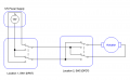
Version #2
In this setup momentary switch Sw1 is pressed and latched at Location 1 sending power to extend the actuator.
Now at location 2 the actuator can be retracted or extended by Sw3.
Before leaving Location 2 fully retract the actuator then press Sw2 to reset RL1 removing power from Sw3.
Finally, set Sw3 back into the extend position.
System is now ready to restart.
1748737788386.png
 

sghioto

Joined Dec 31, 2017
8,673
Do you have a specific recommendation for relay RL1? Thanks in advance! David
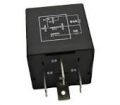
Anyone of those 4 pin auto relays will work.
1748742231763.png

SW2 can be any momentary push button switch with contacts that are normally closed.
Sw1 and Sw2 must be rated for at least 0.25 amps.

1748742255006.png
Sw3 should be rated at 10 amps minimum.
1748742564944.png
 

Tonyr1084

Joined Sep 24, 2015
9,744
How does 12V get from location 1 to location 2?

Location 1:
SW1 has been momentarily pressed.
RL1 is latched.
Actuator has fully extended.

Location 2:
SW2 gets pressed
RL1 unlatches
Actuator gets power - how?
 

Tonyr1084

Joined Sep 24, 2015
9,744
If we're going to use a DPDT switch, why not two? That way there's no need for a relay and the actuator can be fully operated from either location.
Screenshot 2025-06-01 at 8.01.35 AM.png
 

Tonyr1084

Joined Sep 24, 2015
9,744
It doesn't, one would need to go back to Location 1.
Did you read post #22?
Yes, I did. I got the impression, either by statement from the TS or by my making an assumption that location 2 was away from location 1. Having to go back to L1, the TS wouldn't need L2. Not if he's going to go back and forth to operate the actuator. I think we're seeing this from two different points of view.
 

sghioto

Joined Dec 31, 2017
8,673
my making an assumption that location 2 was away from location 1.
Correct, the two locations are appx 10m apart per post #1.
My design is based on what the TS requested but your idea using two DPDT switches will work.
Don't know the purpose of the two locations but would assume the actuator is retracted when leaving Location 2.
 

panic mode

Joined Oct 10, 2011
5,095
the way i see it, operator (location 1) needs push button only. this should be momentary, with latching circuit. operator may not see the actuator.

maintenance controls (location2) need to be able to override operator control and jog actuator in either direction, any time. here no latching is required or wanted since 3500N actuator provides huge force (350kg) while mentioned load is only 2kg.
 

Tonyr1084

Joined Sep 24, 2015
9,744
Correct, the two locations are appx 10m apart per post #1.
My design is based on what the TS requested but your idea using two DPDT switches will work.
Don't know the purpose of the two locations but would assume the actuator is retracted when leaving Location 2.
Guess I missed the 10M part. Sort of similar to your assumption, I imagined opening a gate or a garage door from location 1 and closing it from location 2. Then being able to open the gate or garage door from location 2. But then the problem comes when wanting to close the gate or garage door. Or whatever the TS is wanting to operate.
 

Thread Starter

Davidvee

Joined Jan 13, 2025
9
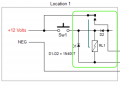
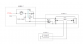
Hello again. An update and questions if I may regarding the wiring of this circuit please. I have not been successful in interpreting and implementing the circuit. In this attached image I have enclosed the area of the circuit that I'm confused about in green from Location 1.
1748822611294.png

I am using all the suggested components including the diodes, 4 pin relay (inputs = 30, 85, 86, 87),
momentary N/C switches (Sw1, Sw2) and DPDT switch. I figure that I am connecting the 4 pin relay incorrectly? Also, I'm also not sure why D1 (connected to NEG) then connects to the POS on the other side of Sw1?

Any advice on correct relay wiring in this scenario would be greatly appreciated! Thank you, David
 

sghioto

Joined Dec 31, 2017
8,673
I am using all the suggested components including the diodes, 4 pin relay (inputs = 30, 85, 86, 87),
momentary N/C switches (Sw1, Sw2) and DPDT switch. I figure that I am connecting the 4 pin relay incorrectly? Also, I'm also not sure why D1 (connected to NEG) then connects to the POS on the other side of Sw1?
Any advice on correct relay wiring in this scenario would be greatly appreciated! Thank you, David
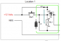
Sw1 is a N/O switch only Sw2 is N/C.
D1 suppresses the EMF or flyback voltage from the relay when it is reset.
Seen below are the correct pin numbers for the relay and diode orientation.
1748829104639.png
 
Last edited:
Top