Facebook
 Google
 GitHub
 Linkedin
I already have that one (came yesterday) but the size is not going to work on my project and that is why I was looking at the L293N asi can make the circuit smaller…?The L293N on the board with ready made interface may prove a little less trouble?")
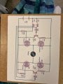
How to reverse motor direction?
- Thread starter esbfggc
- Start date