How to repair three circuit boards for auto ignition neon bulbs tester?

Thread Starter

russwr

Joined Aug 29, 2017
123
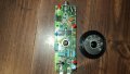
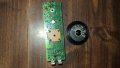
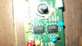
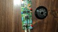
They are three units of Snapon MT2700 high voltage test meters for measuring spark plug high volts using neon bubs with variable resistor. The pots were tested OK. There is small power circuit and led using input 9v battery. None of the boards registers high voltage. The units also show whether positive or negative volts.
 

Attachments

Last edited:

Thread Starter

russwr

Joined Aug 29, 2017
123


The upper 2 red bulbs are the polarity type. Ignition spark can be positive or negative output, depending on arrangement of primary wires of step up autotransformer. The lower bulb is just for the on/off switch. None of the 3 meters work. Cable clip goes to thick insulation of plug wire as pick up. Other cable goes to ground. 9v battery turns on initial bulb. Rotation of pot turns until glowing goes down. At that point, reading is taken of Max high volts. Manufacturer has no repair sheets/ data. I had checked the cables and pots with ohmmeter. Years ago, I had repaired someone's engine timing light. The owner had hooked up the battery clips backwards. The internal large capacitor was charged up backwards. Shorting the cap restored the timing light. I was also recently tinkering with reversed high voltage. - However, the meter was to respond both ways anyway. I read the manual. Electrical parts do deteriorate over time. Does the input NEON bulb on board reduce volts to balance of board? It is not seen on outside of outer case. Only 3 red bulbs available. Maybe Neon is open / unusable?
I had recently purchased the cheap CHINA hand held oscilloscope, the power supply, and voltage reducer probe by 10,000volts. A reading of 3v of screen,would be 30,000v ignition. (open board type, DSO 138 as "welded" only as soldered completed, and probe Hantek HT-25.
 

Thread Starter

russwr

Joined Aug 29, 2017
123
Can this single input Neon bulb be acting as a part of a voltage divider circuit?? Then the neon would be necessary to run the whole board. These 3 test meters are very old.
The farmers use a electric fence test meter for high volts. It has an in series group of neon bulbs with resistors. several bulbs light up depending on the voltage level. Each neon has to be good for the meter to work.
 

Thread Starter

russwr

Joined Aug 29, 2017
123
how does a neon bulb fail to flash?
Neon bulbs can fail in a few different ways:

Filament Burnout: Neon bulbs often have filaments that help start the ionization process. If these filaments burn out, the bulb won’t light up.


  1. Gas Leakage: Neon bulbs contain a small amount of neon gas (or other noble gases). If the bulb gets damaged or the seal fails, the gas can leak out. Without the right gas pressure, the bulb won’t light.

  2. Electrode Wear: Over time, the electrodes inside the bulb can degrade due to the constant electrical discharge. This wear can make it difficult for the bulb to maintain proper ionization.

  3. Electrical Failure: Issues with the power supply or the circuit driving the bulb can cause it to fail. For example, if the transformer or power source malfunctions, the bulb might not receive the correct voltage to operate.

  4. Mechanical Damage: Physical damage to the bulb, such as cracks or breakage, can lead to failure by disrupting the internal environment necessary for the bulb to function.
    Each of these issues can cause the neon bulb to stop lighting or exhibit erratic behavior.
 
Top