How to reduce output ripples for DC/DC converters ?

Thread Starter

Xenon02

Joined Feb 24, 2021
500
I'm dealing with a problem finding a solution to output ripples.

1684244287091.png

How can I reduce this output ripples using imperfect capacitors and imperfect inductors ?
I've tried using 330u Tantalum capacitor but it was imperfect so the series induction made it look like in the picture.


I also have the same problem in other circuits, so maybe someone know how to reduce these output ripples for the Converters
 

Attachments

Thread Starter

Xenon02

Joined Feb 24, 2021
500
Can you share a picture of the circuit please for those of us that cant read .asc files
Of course here it is:

1684246547124.png

The problem is (not only in this converter) that I cannot get rid of the output voltage ripples). I think there is also a huge input voltage ripples as well but when I get rid of output voltage ripples maybe the second problem will be also solved.

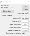
The thing is I added 330uF capacitor on the output but it made it worse, and the elements I have to use imperfect elements except resistors. Like in the example :

1684246742267.png

So maybe someone has a suggestion which capacitor to use that has Inductance and resistance but will help me reduce it to small value the output ripples ? Or maybe suggestion on a different solution.
 

drjohsmith

Joined Dec 13, 2021
852
seems your using the linear tech ( ADI ) power converter tool.
https://www.analog.com/en/design-center/ltpowercad.html
are you measuring the voltage across Rload ?
There was last time I used the tool,the tab to display and add output and input filters,

what is this L5 circuit aiming to do,is it part of the LT8333 circuit ?
all it seems to be doing to me is adding ouptut resistance between the switch and the smoothing capacitors which is what you dont want to do,
 

Thread Starter

Xenon02

Joined Feb 24, 2021
500
what is this L5 circuit aiming to do,is it part of the LT8333 circuit ?
all it seems to be doing to me is adding ouptut resistance between the switch and the smoothing capacitors which is what you dont want to do,
I took the L5 and L4 from the datasheet

1684248998304.png

Of course I've added the flux that determines the inductance value for the inductor and it also must stay ;)

1684249134856.png

The resistance is 51mOhm, and the Capaitance is really small.
But when I add the capacitor that has imperfect inductance in him then the outputthen it creates a huge output ripple but when I set the inductance in capacitor to 0 then there are very small ripples, but I think every capacitor has a small inductance so maybe there is another solution on how to reduce those ripples.

seems your using the linear tech ( ADI ) power converter tool.
https://www.analog.com/en/design-center/ltpowercad.html
are you measuring the voltage across Rload ?
There was last time I used the tool,the tab to display and add output and input filters,
I'm a begginer in LTSpice so I don't know what to use to filter the output using the imperfect components.
 

drjohsmith

Joined Dec 13, 2021
852
I took the L5 and L4 from the datasheet

View attachment 294325

Of course I've added the flux that determines the inductance value for the inductor and it also must stay ;)

View attachment 294327

The resistance is 51mOhm, and the Capaitance is really small.
But when I add the capacitor that has imperfect inductance in him then the outputthen it creates a huge output ripple but when I set the inductance in capacitor to 0 then there are very small ripples, but I think every capacitor has a small inductance so maybe there is another solution on how to reduce those ripples.


I'm a begginer in LTSpice so I don't know what to use to filter the output using the imperfect components.
well, did not know that
yep looked in the data sheet, did not realize one can use this part for voltage inversion.

looking at the plot you showed,
which voltage are you showing ?
do you have output filtering on this plot ?
 

Thread Starter

Xenon02

Joined Feb 24, 2021
500
looking at the plot you showed,
which voltage are you showing ?
do you have output filtering on this plot ?
The voltage was measured in Vout point

1684253699084.png

What output filters ? This is all I have in the circuit.
I've tried to add capacitors to smooth the output (decrease the output ripples) but it didn't work because they had inductance value in each capacitor, but I have to include them.

Here is the comparison in a situation where C12 inductance value is 0

1684253889063.png

But when there is inductance value in C12 then it looks like that :

1684254117220.png
Do you have maybe any suggest how to reduce it ?

As I've mentioned I tried to add some capacitors to reduce it like adding here C2

1684254222117.png

Then it looks the same.

1684254296825.png

So I am having a hard time trying to find a solution.
 

drjohsmith

Joined Dec 13, 2021
852
The voltage was measured in Vout point

View attachment 294334

What output filters ? This is all I have in the circuit.
I've tried to add capacitors to smooth the output (decrease the output ripples) but it didn't work because they had inductance value in each capacitor, but I have to include them.

Here is the comparison in a situation where C12 inductance value is 0

View attachment 294335

But when there is inductance value in C12 then it looks like that :

View attachment 294337
Do you have maybe any suggest how to reduce it ?

As I've mentioned I tried to add some capacitors to reduce it like adding here C2

View attachment 294338

Then it looks the same.

View attachment 294339

So I am having a hard time trying to find a solution.
what strikes me,is not so much that you need filtering,
but that the output voltage is not stable,it seems to still be dropping,
what happens if you run the simulation for say 2 seconds,
I'd suggest that you start of with a step back ,with the default circuit that comes with the lt power cad link above
that seems to be only for a +ve output, but it will give you confidence in the system and your understanding of spice.

then go back into your spice, and try the same circuit, then add the -ve output option
small steps..

You will need a good few 100 uF of capacitance on the output
but power cad can help you design that

I'd also for a starter,not worry about none perfect compoentns
yes when you move on , you will, but to get the basic circuit working first , just use perfect parts,
 

Thread Starter

Xenon02

Joined Feb 24, 2021
500
I'd also for a starter,not worry about none perfect compoentns
yes when you move on , you will, but to get the basic circuit working first , just use perfect parts,
Unfortunatelly I have to use them, this is part of my project ;)


what strikes me,is not so much that you need filtering,
but that the output voltage is not stable,it seems to still be dropping,
what happens if you run the simulation for say 2 seconds,
I'd suggest that you start of with a step back ,with the default circuit that comes with the lt power cad link above
that seems to be only for a +ve output, but it will give you confidence in the system and your understanding of spice.
Oh you mean the output is still dropping, well of course it is because I only showed part of this simulation, it reaches it's stable point in -11V, but the ripples are just to big.

Here is another example where it reaches 11V instead of -11V

1684256210674.png

1684256226952.png

They are from the same circuit but different scalling.

1684256261422.png

The circuit.


So reaching the stable point isn't the problem, only the ripples are the problem.
 

drjohsmith

Joined Dec 13, 2021
852
Sorry
general in engineering, we only build upon tests , and things like "of course" are not of benefit.

I was asking about the end voltage, as one of the many problems in DCDC, is the thing being un stable,and never meeting regulation.

The dc voltage is only valid once your in regulation , which seems to be about , who knows as you have not shown us, changed the chip, and have gone your own way
If you want to do this different , please carry on and I'll leave it to others.
 
Top