 Facebook
 Google
 GitHub
 Linkedin
Hi all,
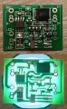
I recently bought a solar lamp circuit from AliExpress. The board requires three peripheral components - a li-ion battery, a solar cell, and an LED. The board has a constant current output to the LED of 300mA (output voltage of 2V - 3.3V).
I'd like to use it to drive about 60mA to an LED, and so I need to reduce the board's 300mA output. I know that the simple option is to use a current limiting resistor, but this would be inefficient (power would be wasted in the resistor). So, I'd like to try to modify the circuit board so that it produces a lower output current.
I've created a circuit diagram of the board (although many of the components don't have identifying markings), and I've taken photos of the board and attached them.
Can anyone figure out which components supply the output current, and how to change the current? (I'm assuming that one of the board's resistors is used to set the current).
Many thanks, and please contact me if you need any further details,
Andrew.
Attachments
-
 16.8 KB Views: 63
 -
 784.7 KB Views: 59


