Facebook
 Google
 GitHub
 Linkedin
https://www.onsemi.com/pdf/datasheet/2n3903-d.pdf
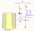
Link above are the datasheet for the transistor 2N3903/2N3094.
(1) May I ask if my Ic (Collector Current) is 35.7mA, what is the base current I should used?
(2) May I ask how do I read the gain from the table below ? Do I need to concern about this when calculating my Ib (base current)?
(3) For example my Ib (base current) is 4.3mA, what will the gain of the transistor be? Because there are multiple gain shown in the table.
Thanks in advance as I am stuck designing my circuit as i have no idea how to read the ON Characteristics table.