 Facebook
 Google
 GitHub
 Linkedin
How to limit current flowing through LM317
- Thread starter iinself
- Start date
Scroll to continue with content
iinself,
The LM317 regulates the output voltage based on a sample of that voltage from two resistors. The problem the circuits you linked to have is that the actual output is not the LM317 output - there are components between the two points. So they may work OK, and provide the current you want, but they may also not be regulated as well because the actual output is not being sensed. Look at the high-current circuit in the datasheet: there's an NPN transistor above the LM317 which passes the extra current, but you'll notice that the voltage output to whatever circuit is still the LM317 output, and is still sensed via two resistors.
The LM317 regulates the output voltage based on a sample of that voltage from two resistors. The problem the circuits you linked to have is that the actual output is not the LM317 output - there are components between the two points. So they may work OK, and provide the current you want, but they may also not be regulated as well because the actual output is not being sensed. Look at the high-current circuit in the datasheet: there's an NPN transistor above the LM317 which passes the extra current, but you'll notice that the voltage output to whatever circuit is still the LM317 output, and is still sensed via two resistors.
I understand, can you please explain what is the function of the PNP transistor in the high current circuit of the datasheet. Why can't we connect the base of the NPN transitor to input of LM317? How can we calculate the power rating of the 22R Thanks.iinself,
The LM317 regulates the output voltage based on a sample of that voltage from two resistors. The problem the circuits you linked to have is that the actual output is not the LM317 output - there are components between the two points. So they may work OK, and provide the current you want, but they may also not be regulated as well because the actual output is not being sensed. Look at the high-current circuit in the datasheet: there's an NPN transistor above the LM317 which passes the extra current, but you'll notice that the voltage output to whatever circuit is still the LM317 output, and is still sensed via two resistors.
Now it appears that you are talking about different schematics at different points. Could you please clarify which schematic applies to which part of post?I understand, can you please explain what is the function of the PNP transistor in the high current circuit of the datasheet. Why can't we connect the base of the NPN transitor to input of LM317? How can we calculate the power rating of the 22R Thanks.
I am trying to understand the need for the PNP transitor at the bottom. Also how to calculate the power rating of 22R. thanks.Now it appears that you are talking about different schematics at different points. Could you please clarify which schematic applies to which part of post?
Attachments
-
 29.8 KB Views: 129
I'd guess because of the dropout voltage. If you connect the base to the input and the emitter to the output there'd be only about .7V across the regulator. It needs at least 3V I think. As for the resistor I don't know; I'm not sure how the current would be shared between the regulator and the pass transistor. You could find a SPICE model and simulate it.I understand, can you please explain what is the function of the PNP transistor in the high current circuit of the datasheet. Why can't we connect the base of the NPN transitor to input of LM317? How can we calculate the power rating of the 22R Thanks.
So the first thing is to understand the basic idea behind how this circuit works.I am trying to understand the need for the PNP transitor at the bottom. Also how to calculate the power rating of 22R. thanks.
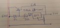
Your output, Vo, gets current from three sources -- the regulator output, the collector of the 2N2905 PNP transistor and the emitter of the TIP73 transistor.
If the Vbe of the PNP transistor is less than 0.6V (roughly, let's just assume that Vbe of the transistors are fixed at 0.6V when on), the if no current is flowing in the 22Ω resistor the PNP transistor will be OFF. If that transistor is OFF, then the NPN transistor will also be OFF. That means that small currents all come from the regulator. But whatever current does from the regulator is pulled through the 22Ω resistor and once this current is enough to cause a drop of 0.6V across it, the PNP transistor will start to turn on. This will happen when the current get up to about 27.3 mA. So we see what the roll of the 22Ω resistor is -- it sets the amount of baseline current that the regulator will deliver directly. The bigger we make this resistor, the less current it will supply before turning on the bypass transistors.
So what happens after we reach 27.3 mA?
Well, we start getting some base current in the PNP transistor which is than amplified by the transistor beta to yield some collector current. At first, this collector current must go through the 500Ω resistor because no current will go into the base of the NPN transistor until we get 0.6V developed across the 500Ω resistor. This will require only about 1.2 mA. The amount of current that will go through the 5kΩ base resistor (and on out the regulator) is pretty negligible. Let's say that both transistors have a beta of 20, that would only mean a small fraction of a milliamp for the base resistor. Why 500Ω? Probably no critical reason -- we want something there so that leakage current through the PNP won't turn on the NPN. We could probably use something significantly smaller or significantly larger and not see a huge impact on performance. If we make it too big we might induce some instability. So let's just go with 500Ω unless we see a reason to change it.
So what happens after we reach 28.5 mA?
Now we start injecting base current into the NPN transistor and essentially all of the rest of the load current comes through it.
To see how good (or not good) this analysis is, let's see how much current will come through each branch if the load current is 2000 mA, the output voltage is Vo=5V, and the input voltage, Vi, is 20V. Let's assume that the transistor betas are both 20.
If all 2000 mA flows through the NPN, then the base current would need to be 100 mA. Now we can appreciate why we have to transistors -- the base current requirements of a single transistor would be pretty high (given the low beta of power transistors), so we stack two of them to multiply the betas. The collector current of the PNP would then be about 101 mA and it's base current would be about 5.1 mA. That means that the voltage at the input of the regulator will be 20V - 0.6V - 5kΩ·5.1mA = -5.56V. Well, there we have a problem because the input to the regulator needs to stay at least a couple volts about Vo (you'd have to check the data sheet to see what the maximum dropout voltage spec is, but 2V is a pretty good number of our purposes). Now we see what the roll of the 5kΩ resistor is -- it sets a soft current limit ('soft' because it is dependent on the transistor betas, which is not well known). Let's say we want to limit out at Vi=7V. That means that the voltage across the base resistor needs to be no more than 20V - 0.6V - 7V = 12.4V. So we want that resistor to be about 12.4V/5.1mA=2.43kΩ. So let's use a 2.2kΩ resistor. At this point we have 13V across the 22Ω resistor which means that we have 591 mA flowing in it and about another 5mA from the base resistor so about 600mA. Let's say that we want to keep the regulator current down in the 100mA range at max. That would require a 137Ω resistor. Let's use a 180Ω resistor to give us some margin.
So with these sizes picked, what is our maximum output current? At a dropout of 2V, our input resistor has 13V/180Ω=72.2mA. Our base resistor has 12.4V/2.2kΩ=5.6mA. So the regulator is supplying 77.8mA. The PNP has a collector current of 20·5.6mA=112mA. About 1.2mA of this goes through the 500Ω resistor and on to the load, so that's 79.0mA. The remaining 110.8mA goes through the NPN and gets multiplied by (beta+1) which produces 2327mA for a total of about 2400mA. The actual limit will probably be quite a bit more because the actual transistor gains are likely quite a bit higher than 20.
As for the power ratings, you now have all the information needed to calculate the power dissipation of all the major components.
Hopefully that gives you a game plan to work the numbers for your circuit particulars.
The PNP is required to get the proper output polarity of the boost circuit.I am trying to understand the need for the PNP transitor at the bottom. Also how to calculate the power rating of 22R. thanks.
When the voltage drop across the 22R, due to the load current, reaches about 0.65V (@30mA) the PNP will start to turn on which, in turn, starts to turn on the NPN diverting the load current around the LM317 and into the load.
Depending upon the current you could eliminate the NPN and just use a power PNP.
Note that the power transistor (either the NPN or the PNP) must be on a heat sink to dissipate the power from dropping the voltage.
The power dissipated in the 22R is only (.65^2)/22 = 20mW.
Thank you, thank you.So the first thing is to understand the basic idea behind how this circuit works.
Your output, Vo, gets current from three sources -- the regulator output, the collector of the 2N2905 PNP transistor and the emitter of the TIP73 transistor.
If the Vbe of the PNP transistor is less than 0.6V (roughly, let's just assume that Vbe of the transistors are fixed at 0.6V when on), the if no current is flowing in the 22Ω resistor the PNP transistor will be OFF. If that transistor is OFF, then the NPN transistor will also be OFF. That means that small currents all come from the regulator. But whatever current does from the regulator is pulled through the 22Ω resistor and once this current is enough to cause a drop of 0.6V across it, the PNP transistor will start to turn on. This will happen when the current get up to about 27.3 mA. So we see what the roll of the 22Ω resistor is -- it sets the amount of baseline current that the regulator will deliver directly. The bigger we make this resistor, the less current it will supply before turning on the bypass transistors.
So what happens after we reach 27.3 mA?
Well, we start getting some base current in the PNP transistor which is than amplified by the transistor beta to yield some collector current. At first, this collector current must go through the 500Ω resistor because no current will go into the base of the NPN transistor until we get 0.6V developed across the 500Ω resistor. This will require only about 1.2 mA. The amount of current that will go through the 5kΩ base resistor (and on out the regulator) is pretty negligible. Let's say that both transistors have a beta of 20, that would only mean a small fraction of a milliamp for the base resistor. Why 500Ω? Probably no critical reason -- we want something there so that leakage current through the PNP won't turn on the NPN. We could probably use something significantly smaller or significantly larger and not see a huge impact on performance. If we make it too big we might induce some instability. So let's just go with 500Ω unless we see a reason to change it.
So what happens after we reach 28.5 mA?
Now we start injecting base current into the NPN transistor and essentially all of the rest of the load current comes through it.
To see how good (or not good) this analysis is, let's see how much current will come through each branch if the load current is 2000 mA, the output voltage is Vo=5V, and the input voltage, Vi, is 20V. Let's assume that the transistor betas are both 20.
If all 2000 mA flows through the NPN, then the base current would need to be 100 mA. Now we can appreciate why we have to transistors -- the base current requirements of a single transistor would be pretty high (given the low beta of power transistors), so we stack two of them to multiply the betas. The collector current of the PNP would then be about 101 mA and it's base current would be about 5.1 mA. That means that the voltage at the input of the regulator will be 20V - 0.6V - 5kΩ·5.1mA = -5.56V. Well, there we have a problem because the input to the regulator needs to stay at least a couple volts about Vo (you'd have to check the data sheet to see what the maximum dropout voltage spec is, but 2V is a pretty good number of our purposes). Now we see what the roll of the 5kΩ resistor is -- it sets a soft current limit ('soft' because it is dependent on the transistor betas, which is not well known). Let's say we want to limit out at Vi=7V. That means that the voltage across the base resistor needs to be no more than 20V - 0.6V - 7V = 12.4V. So we want that resistor to be about 12.4V/5.1mA=2.43kΩ. So let's use a 2.2kΩ resistor. At this point we have 13V across the 22Ω resistor which means that we have 591 mA flowing in it and about another 5mA from the base resistor so about 600mA. Let's say that we want to keep the regulator current down in the 100mA range at max. That would require a 137Ω resistor. Let's use a 180Ω resistor to give us some margin.
So with these sizes picked, what is our maximum output current? At a dropout of 2V, our input resistor has 13V/180Ω=72.2mA. Our base resistor has 12.4V/2.2kΩ=5.6mA. So the regulator is supplying 77.8mA. The PNP has a collector current of 20·5.6mA=112mA. About 1.2mA of this goes through the 500Ω resistor and on to the load, so that's 79.0mA. The remaining 110.8mA goes through the NPN and gets multiplied by (beta+1) which produces 2327mA for a total of about 2400mA. The actual limit will probably be quite a bit more because the actual transistor gains are likely quite a bit higher than 20.
As for the power ratings, you now have all the information needed to calculate the power dissipation of all the major components.
Hopefully that gives you a game plan to work the numbers for your circuit particulars.
Thanks.The PNP is required to get the proper output polarity of the boost circuit.
When the voltage drop across the 22R, due to the load current, reaches about 0.65V (@30mA) the PNP will start to turn on which, in turn, starts to turn on the NPN diverting the load current around the LM317 and into the load.
Depending upon the current you could eliminate the NPN and just use a power PNP.
Note that the power transistor (either the NPN or the PNP) must be on a heat sink to dissipate the power from dropping the voltage.
The power dissipated in the 22R is only (.65^2)/22 = 20mW.
The voltage across the 22Ω is not clamped at 0.65V. As more current is passed by the transistors, more base current flows in that 5kΩ resistor which raises the voltage and current through the 22Ω resistor. At the limit, the voltage across it is the input voltage to the circuit as a whole minus the minimum input voltage to the regulator before dropout. This can result in considerable power in this resistor. In the example I used, the power dissipation could exceed 7.5W.The power dissipated in the 22R is only (.65^2)/22 = 20mW.
Below is the simulation of a boosted LM317 circuit using one PNP power transistor showing the output voltage and current for a varying load resistance, R4.
The addition of R5 is to provide some current limiting under short circuit conditions to help avoid zapping the transistor.
R5 is a low resistance value which can be provided by 1 foot of 24AWG copper wire. If you want to fold the wire, do it in a zig-zag fashion to minimize inductance.
Note that, for this circuit, both the power transistor and the LM317 need to be on a heat-sink.
R1 should be a 2W resistor.
Attachments
-
1.2 KB Views: 86
Thanks.Below is the simulation of a boosted LM317 circuit using one PNP power transistor showing the output voltage and current for a varying load resistance, R4.
The addition of R5 is to provide some current limiting under short circuit conditions to help avoid zapping the transistor.
R5 is a low resistance value which can be provided by 1 foot of 24AWG copper wire. If you want to fold the wire, do it in a zig-zag fashion to minimize inductance.
Note that, for this circuit, both the power transistor and the LM317 need to be on a heat-sink.
R1 should be a 2W resistor.
View attachment 80286
Again I appreciate your inputs.The voltage across the 22Ω is not clamped at 0.65V. As more current is passed by the transistors, more base current flows in that 5kΩ resistor which raises the voltage and current through the 22Ω resistor. At the limit, the voltage across it is the input voltage to the circuit as a whole minus the minimum input voltage to the regulator before dropout. This can result in considerable power in this resistor. In the example I used, the power dissipation could exceed 7.5W.
I am trying to bring down 60V to 50V, in an effort not to blow up the LM317, I am trying to keep the current through it minimal but I also want the voltage differential between its input and output minimum. Is it possible to use a 10V 1W zener in series before the regulator for this purpose? My current requirement about 7A.
The beta for the transistor is only 30, I was looking at TIP120 which is NPN
Attachments
-
 10.1 KB Views: 62
Last edited:
I am a bit confused? Since the resistor has to follow ohms law - the forward bias voltage of Base emitter can be I think a max of about .7V, how can more current flow through 22R. It has to be around .03A isn't it?The voltage across the 22Ω is not clamped at 0.65V. As more current is passed by the transistors, more base current flows in that 5kΩ resistor which raises the voltage and current through the 22Ω resistor. At the limit, the voltage across it is the input voltage to the circuit as a whole minus the minimum input voltage to the regulator before dropout. This can result in considerable power in this resistor. In the example I used, the power dissipation could exceed 7.5W.
Last edited:
Why does R1 need to be rated for 2W? It should only have about 1.3V/220Ω or ~6mA of current flowing in it. That's only 23 mW.Below is the simulation of a boosted LM317 circuit using one PNP power transistor showing the output voltage and current for a varying load resistance, R4.
The addition of R5 is to provide some current limiting under short circuit conditions to help avoid zapping the transistor.
R5 is a low resistance value which can be provided by 1 foot of 24AWG copper wire. If you want to fold the wire, do it in a zig-zag fashion to minimize inductance.
Note that, for this circuit, both the power transistor and the LM317 need to be on a heat-sink.
R1 should be a 2W resistor.
View attachment 80286
Do you mean R3? I get about 1.5W for that one (but that's assuming that all of the Iout from the regulator is going through it, and a good portion of that is probably base current in the PNP), so 2W would be quite reasonable.
For this you have no problems. The 40V max rating is for the Vin to Vout differential voltage. You only have 10V. Keep in mind that the part only knows the voltage differences at its three pins. The voltage difference between the out pin and the adjust pin is only about 1.25V, so the big one is between Vin and Vout (technically between Vin and Vadj, but that's not how it's spec'ed). Now, if you need to allow for the possibility of a short circuit output, then the 60V comes back into play.I am trying to bring down 60V to 50V, in an effort not to blow up the LM317, I am trying to keep the current through it minimal but I also want the voltage differential between its input and output minimum. Is it possible to use a 10V 1W zener in series before the regulator for this purpose? My current requirement about 7A.
Let's plan for 10A to give you some overhead keep the power dissipation in the LM317 low enough so that you don't need a heatsink. If you are using a TO-220 case then the thermal resistance is 80°C/W and you have a max junction temperature of 125°C. If the ambient air is 25°C then that lets you dissipate 1.25W. Let's not push it to the limit and keep thing to 1W. Let's estimate that our peak power dissipation will be when the voltage across the device is about halfway between dropout and the max differential, so about 6V. That means that the current at that point could be about 167mA. Let's be conservative and shoot for no more than 150 mA. With a need for 7A you are going to have a pretty low current gain of perhaps only 10 (probably between 15 and 25, but you need to plan for the minimum, so let's use 10). That means that the base current for the NPN is going to be need to absorb a base current of about 7A/10 or 700mA. That exceeds the max current of 600mA for the 2N3905, but let's say that we're willing to abuse this part because we're pretty sure our actual gain for the NPN will be at least 12. The 2N2905 has a minimum beta of 30 at 500mA and 10V, so that's close enough for planning purposes. That means that our base current for the PNP will be about 25 mA of the 150mA that we are allowing through the regulator. So we can size our input resistor to drop 8V (60V - 52V) at a current of 125mA or 64Ω. Let's use 68Ω. That will limit the current through this resistor (assuming we keep the regulator regulating) to about 120mA and put its max power dissipation at 950mW, so a 1W resistor will probably do, since that is worst case, not expected case, but 2W would be much better.
Your base resistor will have about 7.3V across it and you want it to carry 125mA at that point so you need a resistor of not more than 58Ω. Let's make it 47Ω.
You might consider using a PNP in a TO-220 case and you might also consider using two to four NPN transistors (that are properly ballasted) in parallel.
But you don't have a max of 0.7V across the 22Ω resistor. You have 0.7V across the PNP base-emitter junction. The 22Ω resistor is not across the PNP base-emitter junction, it also has the voltage across that base resistor.I am a bit confused? Since the resistor has to follow ohms law - the forward bias voltage of Base emitter can be I think a max of about .7V, how can more current flow through 22R. It has to be around .03A isn't it?
Sorry, my mistake.But you don't have a max of 0.7V across the 22Ω resistor. You have 0.7V across the PNP base-emitter junction. The 22Ω resistor is not across the PNP base-emitter junction, it also has the voltage across that base resistor.
Again thanks for the clear explanation.For this you have no problems. The 40V max rating is for the Vin to Vout differential voltage. You only have 10V. Keep in mind that the part only knows the voltage differences at its three pins. The voltage difference between the out pin and the adjust pin is only about 1.25V, so the big one is between Vin and Vout (technically between Vin and Vadj, but that's not how it's spec'ed). Now, if you need to allow for the possibility of a short circuit output, then the 60V comes back into play.
Let's plan for 10A to give you some overhead keep the power dissipation in the LM317 low enough so that you don't need a heatsink. If you are using a TO-220 case then the thermal resistance is 80°C/W and you have a max junction temperature of 125°C. If the ambient air is 25°C then that lets you dissipate 1.25W. Let's not push it to the limit and keep thing to 1W. Let's estimate that our peak power dissipation will be when the voltage across the device is about halfway between dropout and the max differential, so about 6V. That means that the current at that point could be about 167mA. Let's be conservative and shoot for no more than 150 mA. With a need for 7A you are going to have a pretty low current gain of perhaps only 10 (probably between 15 and 25, but you need to plan for the minimum, so let's use 10). That means that the base current for the NPN is going to be need to absorb a base current of about 7A/10 or 700mA. That exceeds the max current of 600mA for the 2N3905, but let's say that we're willing to abuse this part because we're pretty sure our actual gain for the NPN will be at least 12. The 2N2905 has a minimum beta of 30 at 500mA and 10V, so that's close enough for planning purposes. That means that our base current for the PNP will be about 25 mA of the 150mA that we are allowing through the regulator. So we can size our input resistor to drop 8V (60V - 52V) at a current of 125mA or 64Ω. Let's use 68Ω. That will limit the current through this resistor (assuming we keep the regulator regulating) to about 120mA and put its max power dissipation at 950mW, so a 1W resistor will probably do, since that is worst case, not expected case, but 2W would be much better.
Your base resistor will have about 7.3V across it and you want it to carry 125mA at that point so you need a resistor of not more than 58Ω. Let's make it 47Ω.
You might consider using a PNP in a TO-220 case and you might also consider using two to four NPN transistors (that are properly ballasted) in parallel.
Last edited:
But now I have to ask, how does the PNP conduct with only 27.3ma, since the voltage across developed across the 22R resistor has to be shared between the 5K resistor and the BE junction of the PNP, isnt it? So I guess we need more current through 22RBut you don't have a max of 0.7V across the 22Ω resistor. You have 0.7V across the PNP base-emitter junction. The 22Ω resistor is not across the PNP base-emitter junction, it also has the voltage across that base resistor.
Last edited:
Yes, I meant R3.Why does R1 need to be rated for 2W? It should only have about 1.3V/220Ω or ~6mA of current flowing in it. That's only 23 mW.
Do you mean R3? I get about 1.5W for that one (but that's assuming that all of the Iout from the regulator is going through it, and a good portion of that is probably base current in the PNP), so 2W would be quite reasonable.

| Thread starter | Similar threads | Forum | Replies | Date |
|---|---|---|---|---|
| G | Current Limit for 28A Draw | Power Electronics | 16 | |
|
|
NPN output circuit with current limit | General Electronics Chat | 17 | |
|
|
Inrush current limit using NTC | Power Electronics | 19 | |
| S | How to current limit a DC motor through hardware | General Electronics Chat | 11 | |
| S | 4 Amp current limit for train conversion | Power Electronics | 15 |


