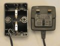
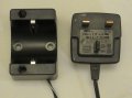
I have one of those B&D screwdrivers. The charging cradle receives its supply via a 1 metre 2-wire cable from a mains plug which incorporates a transformer (old style) with a rated output of 4.5V AC 0.9VA.
Looks good as Ni-cads. Maybe 3 of them for 3.6V?
And simpler to charge than NiMH or Li-ion without burning the house down. @Alec_t just popped in with very important information.
"Your screwdriver and charger are specifically designed to work together."
"Do not attempt to charge any other cordless tool or battery pack with this charger. Do not attempt to charge your screwdriver with any charger other than the one supplied with it."
It is possible that this notice indicates that the circuitry in the screwdriver is designed to work with circuitry in the charger and just connecting up a homemade charger to the screwdriver may not work well. At the very least, you may need to bypass the screwdriver's circuitry and go direct to the batteries.
"Your screwdriver and charger are specifically designed to work together."
"Do not attempt to charge any other cordless tool or battery pack with this charger. Do not attempt to charge your screwdriver with any charger other than the one supplied with it."
That is because it is designed for Nicads.
Besides, all the manufacturers says that to scare you out of your pants.
I made a simple Nicad charger for B&D screw driver that uses small 6 cells.
I think NiCd batteries are a bit more forgiving of charging profile, so rolling your own charger is probably a bit more feasible. But there is still a risk there that can probably be avoided for under $20 -- less when you consider the cost of the parts you will need to make it and even less when you consider even a minimal value on your time.
This might be helpful, but a quick glance indicates that it might also be a bit more complicated than you'd like to tackle. The real question is determining not what is ideal, but what is required and what is "good enough".
I do not think @WBahn wants to close the thread.
He is making a point that novice builders should think twice before building battery chargers. It is not something to take lightly like flashing LEDs.
And it is not something to fight about.
TS is made aware of this and he will learn if he decides to make it.
That is the difficulty in making battery chargers work without exploding the battery
Is it not at least possible that this notice possibly indicates that the circuitry in the screwdriver is designed to work with circuitry in the charger
Then this is good news for the TS. Any needed circuitry, including rectification and monitoring, is in the device (or the battery, but probably not very likely in this case).
Most (maybe even all -- I can't think of any exceptions) of my tool chargers have an integral cord and so you can't lose one with out losing the other. So I've been assuming that the TS only has the drill and has lost the cradle. I therefore also assumed that Alec_t meant that the only thing in the cradle are electrical contacts to the terminals on the screwdriver.
So I think we need two clarifications here:
@Alec_t : When you say the charger is only a mains to 4.5 Vac transformer, are you talking about everything up to and including the cradle, or just the part going from the wall to the cradle?
@Themusicman : When you say you can't locate the power supply, do you mean everything including the cradle, or just the part going from the wall to the cradle?
That's pretty definitive. So the TS should be in pretty good shape. I would not be too surprised if his 5 V wall wart works straight away. If he is willing to risk damaging it he can go ahead and try it. Worst case (well, I supposed a fire is conceivably possible, but highly unlikely) is that it doesn't work and damages the screwdriver and he has to bin it.
Ok, so I took the driver apart and there are 3 batteries in it, but they batteries are unlabelled. There's a diode between the charging connector and one end of the batteries, and the +ve and -ve of the batteries goes straight to the motor through a mechanical forward / reverse lever.
They are circular (tube type) batteries, approx 30mm long and approx 14/15mm diameter, connected in series.
That's pretty definitive. So the TS should be in pretty good shape. I would not be too surprised if his 5 V wall wart works straight away. If he is willing to risk damaging it he can go ahead and try it. Worst case (well, I supposed a fire is conceivably possible, but highly unlikely) is that it doesn't work and damages the screwdriver and he has to bin it.
So, it seems as though I might be able to use a straight 5V wall wart to charge the device.
My next question, is... given there is a diode in the circuit, I assume I need to connect the +ve and -ve the correct way around. When the driver sits in the cradle, there is only one way it will seat correctly, thus adding to my assumption of having to get +ve and -ve the right way around.
So, it seems as though I might be able to use a straight 5V wall wart to charge the device.
My next question, is... given there is a diode in the circuit, I assume I need to connect the +ve and -ve the correct way around. When the driver sits in the cradle, there is only one way it will seat correctly, thus adding to my assumption of having to get +ve and -ve the right way around.

 Facebook
 Google
 GitHub
 Linkedin