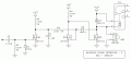
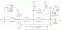
Thanks gents! That AC trigger works beautifully. If the incoming feed is lost, input to the 555 goes high and output then goes low. Mission accomplished in that regard.
Eric, I haven’t plugged your last model into my system yet but I get the idea of using RST pin on the 555 to keep output low once it’s gone there. It’s probably more elegant than my concept of killing power to the 555 and the counter when the relay opens.
Aside from the elegance of it, are there any other benefits to doing it that way? As it stands, my model is working, just with the addition of the AC trigger. Should I change it to use the RST, as per your last model Eric? Or should I just keep it as it is? Am I missing any other potential failures?
hi edge,
I would add the RST modification, this will ensure that if the 90Hz source fails or falls too low in frequency the relay will open and stay open until Manual PB pressed.
It will also ensure that when the project is powered up, the 555 will be in a known Reset state.
The wiring to the double pole switch is simpler.
You show the AC coupling as 10uF.? it should be around 10nF thru 47nF
On the +5V rail output from the 7805 add a 100nF and 47nF cap to 0v, ie; filter the +5V rail, also a 100nF on the 7805 input is recommended.
If the operation of pump causes electrical noise on the power rails add a Diode or Res/Cap snubber across the pump.
Unless I'm missing something, when the circuit removes power from the pump it also removes its own power, effectively latching off the circuit until the switch is pressed again. This removes power from the 4020 but not its clock input, meaning its input is being driven above its Vdd pin - *not* a good thing for that generation of CMOS parts.
I had the same thought as Eric's comment in post #17. I would leave the LED connected to Q8. but drive the timer with Q0 (Q1 on the datasheet). You could reduce the 100 uf electrolytic timing capacitor to a 1 uF ceramic, almost always a good thing - way better long-term reliability.
10nF is probably ok for the capacitive feed to the Trig pin, but I'd suggest a higher value than 4k7 for its pull-up, to ensure the timing cap gets fully discharged by the NPN. The Trig pin might also benefit from a reverse-biased pull-up diode to avoid over-stressing it when it is driven above the supply rail by the cap.
10 nF would be a time constant of 47 us. Seems a bit short for discharging a 100 uF cap. Other than being an electrolytic, does the larger cap value cause any problems?
Agree. This problem goes away if the 2907 (?) transistor (reference designators?) is changed to an NPN to short the cap to GND as a saturated switch rather than an emitter follower. Vcc is only 5 V, so base-emitter reverse breakdown should not be a problem.
Hi AK,
The circuit works OK with 10n, but I have suggested a 47nF if the Trig pulse in not effective with a 10nF.
The other point is the CMOS 4020 output pin driving a 10uF, thats not I would do if the design was mine.
I have given the TS guidance that he should control the 555 RST pin , not switch the +5V rail On/Off.
The circuit the TS has posted should be redesigned.
E
BTW: OT.
Did the other TS get the railway track switching IR project working, I have not heard any news.?
hi edge,
Try increasing the 10nF to say 47nF, lets know how it goes.
If you have a problem post a clear photo shot of the project so that we can check your wiring.
E
Update:
Check the 7805 input wiring on your diagram!
You have left out the 10nF/47Nf on your diagram.
Place a 10k resistor from the reset pin to ground.
Place a 100 ohm resistor from the reset pin to the output pin.
Place a small cap across the 10k.
Place a NO push button from the reset pin to positive.
When the circuit is first powered up, the cap brings the 555 output low.
When you press the button the reset line goes high enabling the 555.
If the signal is present the 555 output replaces the push button, and the 555 remains enabled.
Remove the signal the 555 goes low and disables the 555.
Ditch the low voltage 4020 and replace with a CD4020BE, and get rid of the regulator. (adjust your LED resistors accordingly)
Place your pump running LED across the pump.
Replace the pump relay with a SSR, much more reliable when being jostled around in flight.
Eliminates:
2 transistors…The reset one and the relay drive. (555 can drive SSR directly, even low power version) Regulator and its baggage
Multiple mechanical relays
REMF diode
Agree. This problem goes away if the 2907 (?) transistor (reference designators?) is changed to an NPN to short the cap to GND as a saturated switch rather than an emitter follower. Vcc is only 5 V, so base-emitter reverse breakdown should not be a problem.
The problem with the 555 - well, where to begin - ? ? ?
There are two classic types of monostable multivibrator circuits, true and retriggerable. A problem with the 555 is that its standard monostable circuit is neither. Unlike a true monostable, the output pulse width is not completely independent of the input pulse width. This is why an extra trigger input coupling capacitor is needed. And unlike a classic retriggerable, the output pulse timing does not restart with each trigger event within the timing period.
Separate from that, a problem with most frequency discriminators (missing pulse detector) is noise and confusion when the input freq is very close to the detection threshold freq. Depending on the circuit, the output signal can have full-amplitude noise bursts. Eric's idea of driving the reset input is interesting, but I'm not sure how the circuit will behave at startup.
To address all of that, here is an alternate theory of the crime. Timing component values are approximate. R2 is the critical one to set the detection threshold; the other two resistors are not critical, and can be the same value to simplify the BOM. For C4, I prefer larger decoupling caps in industrial/automotive applications.
This circuit has a very well-behaved output that latches to the error state with the first half-cycle that is below threshold and stays there no matter what the input does later. Also, it does not rely on the motor power relay for its own reset function. The static current in the latched-off state is approx 1 uA, so there is no need to remove power except to force a system reset. The minimum power-off time for a reset is under 0.1 s.
This circuit still does not have input protection, but5 as above it isn't needed if the power source is not switched off with the motor, But input protection could be combined with U1A and D1. I think the timing circuit and latch can be replaced with three transistors. Hmmm ...
There is no sync. That is, all of the outputs from the counter are symmetrical square waves, all with much longer periods (and half-periods) that the input waveform. For any given 4020 positive clock edge input, outputs will go high or low depending on the previous count value. Within the delays of a ripple counter, they all chage state at the same time; but they do not all change in the same direction.
This is a missing *pulse* detector, not a missing *phase* detector. As the input signal decreases in frequency, both the positive and negative half-cycle periods that the 555 sees increase identically. Which one the 555 uses for detection is irrelevant.
The circuit is designed to hold the trigger low while the cap is discharged.
Changing the discharge transistor to NPN means the cap is discharged while the trigger is high.
EDIT:
But a simple reconfiguration would take care of the problem by placing both the cap and trigger on the collector, instead of having the trigger at the base and the cap on the emitter.
I understand you are a novice, and circuits on this forum tend to become more and more complicated, that's why I decided to break my silence and make the suggestions in post #40 designed to simplify things.
Yes, using a sim if fine, just be sure to prove the circuit in a prototype before placing in your airplane.
I would also suggest placing a manual SPST switch across whatever kind of relay you end up using...just in case.
Well, let me say this about that. Here is an all-transistor version. R1-C1-D1 detect the input signal so it can freeze at any voltage and Q1 will see the failure. R2-C2 set the frequency (missing pulse width) detection threshold. Q2 and Q3 are the flipflop to latch the error state, and Q3 does double duty as the relay driver. SW1 resets the circuit.
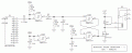
OK, probably the last one. I've used the ULN200x series parts in many projects, and almost all of my automotive projects. Basically, the part is seven open-collector inverters, each rated for 50 V and 0.5 A.
C2 is all there is to the input protection and dead-signal detection, because the pull-down resistor and catch diode are built into U1A. R1-C1 are the timer and U1B is the comparator, to form the frequency discriminator. U1C and D are the latch, plus U1C is the relay driver. SW1 is the reset switch.
The insert is the schematic for each of the seven stages. Because these are simple darlington transistors, no decoupling capacitor is needed. And with base pull-down resistors built in, unused inputs do not have to be tied to anything. And no voltage regulator. And the relay coil suppression diode is built-in.
The only drawback is the relatively low input impedance, which increases the size of the timing capacitor C1.

 Facebook
 Google
 GitHub
 Linkedin