how to find out the base resistor base value?

Thread Starter

Sangpo Sangpo

Joined Jan 22, 2019
4
Hi sir and madam,
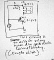
I m trying try making auto light on/off using follwing componets.
1. power source 12 dc volt
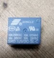
2.Relay 12 volt dc
3.Transistor BC547 1 no.
4.LDR
5. Resistor to base of transistor.
Please teach me how to find the value of resistor to base.
Thank you
.
 

ericgibbs

Joined Jan 29, 2010
18,766
hi SS,
Welcome to AAC.
Do you have a type name for the LDR, they vary in their specification, so the Base resistor is chosen to suit the LDR.
You may also have to use a variable resistor with the LDR, so that the light is on/off at the required light levels.
E
 

MisterBill2

Joined Jan 23, 2018
18,167
The base resistor value would be chosen to limit the base current to the amount needed to assure transistor saturation at the current required to energize the relay that you are using, and to provide that base current under all of the conditions that the system will be operating in. Much of this determination can be done on paper, if you have the data sheet about the transistor, and if you know the operating current requirement of the relay. If the relay is connected as a collector load the calculations are not hard.
Then determining the base current required can follow next, based on transistor gain and the required collector current at the lowest temperature the system will experience. Determining the base series resistor requires that you know the resistance of that LDR at the light level that you want the relay to switch on. That will be a bit more complicated, because you also need to know the light level at which you want the relay to switch off. And the base current for the relay to release will be less than that for it to switch on.
The circuit will probably be more complex than just the LDR and a resistor in series from the 12 volts source to the base of the transistor, unless the LDR resistance changes a very large amount with the change in light intensity.
So you will need to describe the actual circuit that you are intending to use for a description of the parts values to make sense.
 

Dodgydave

Joined Jun 22, 2012
11,284
For saturation of 100mA Collector current, try a 100K Base resistor.

There are three versions of this transistor, A, B, C.
 

Thread Starter

Sangpo Sangpo

Joined Jan 22, 2019
4
hi SS,
Welcome to AAC.
Do you have a type name for the LDR, they vary in their specification, so the Base resistor is chosen to suit the LDR.
You may also have to use a variable resistor with the LDR, so that the light is on/off at the required light levels.
E
 

Thread Starter

Sangpo Sangpo

Joined Jan 22, 2019
4
For saturation of 100mA Collector current, try a 100K Base resistor.

There are three versions of this transistor, A, B, C.
Thank you for your clarification
1. Transistor type: bc547 b.
2. Relay : 12 v and 10 am
How ever i would apprciate you if you show me the step by step by calculation to get 100k base resistor.
thank
hi SS,
Welcome to AAC.
Do you have a type name for the LDR, they vary in their specification, so the Base resistor is chosen to suit the LDR.
You may also have to use a variable resistor with the LDR, so that the light is on/off at the required light levels.
E
 

Thread Starter

Sangpo Sangpo

Joined Jan 22, 2019
4
here are three versions of this transistor, A, B, C.[/QUOTE]
Thank you for your clarification
1. Transistor type: bc547 b.
2. Relay : 12 v and 10 am
How ever i would apprciate you if you show me the step by step by calculation to get 100k base resistor.
thank
The base resistor value would be chosen to limit the base current to the amount needed to assure transistor saturation at the current required to energize the relay that you are using, and to provide that base current under all of the conditions that the system will be operating in. Much of this determination can be done on paper, if you have the data sheet about the transistor, and if you know the operating current requirement of the relay. If the relay is connected as a collector load the calculations are not hard.
Then determining the base current required can follow next, based on transistor gain and the required collector current at the lowest temperature the system will experience. Determining the base series resistor requires that you know the resistance of that LDR at the light level that you want the relay to switch on. That will be a bit more complicated, because you also need to know the light level at which you want the relay to switch off. And the base current for the relay to release will be less than that for it to switch on.
The circuit will probably be more complex than just the LDR and a resistor in series from the 12 volts source to the base of the transistor, unless the LDR resistance changes a very large amount with the change in light intensity.
So you will need to describe the actual circuit that you are intending to use for a description of the parts values to make sense.

Thank you MISTER BILL2 for your explanation.
Since im very new to this filed, I will be happy if show me the simple steps how would you do the calculation
1. Transistor type: bc547 b.
2. Relay : 12 v and 10 am
How ever i would apprciate you if you show me the step by step by calculation to get 100k base resistor.
thank
 

Dodgydave

Joined Jun 22, 2012
11,284
The transistor A type has an hfe of 100.

So you're using 12V, the b/e voltage is 0.7, that's 11.3V across the resistor.

You need to operate the transistor at maximum current of 100mA, divided by hfe gives 1mA current , with 11.3V gives 113K, better to use a lower value like 100K to 110K.
 
Last edited:

Alec_t

Joined Sep 17, 2013
14,280
The usual rule of thumb for a transistor operating as a switch is to have a base current about 1/20 to 1/10 of the collector current. This ensures that, regardless of the particular transistor used, it will operate in the saturated state.
What is the required pull-in coil current (not the contact rated current) of your relay?
 

MisterBill2

Joined Jan 23, 2018
18,167
I am thinking that for the relay the coil is rated for 12 volts and the contact maximum current is ten amps. A relay with a coil that requires 10 A is quite a big relay. Do you have a brand name and model number for the relay? I am doubting that the coil current of that relay is 10 amps, but that the ten amps is the contact rating instead.
To calculate the base current limiting resistor the first thing to know is the maximum collector current for which the transistor must be fully switched on, meaning that the collector to emitter voltage is the minimum possible because the transistor is saturated. That is the Ic term. That number is then divided by the gain term, Hfe, which tells the base current that must flow to allow the required collector current to flow. From the data sheet Dave has determined that the base voltage wit the transistor saturated for the required collector current will be 0.7 volts, relative to the emitter. Unfortunately, without some understanding of the circuit arrangement and how the LDR is part of the circuit there is no way to guess what the value of that resistor must be. Dave has calculated the value for a circuit with the resistor connected to the same +12 volt supply, but that does not allow for any effect contributed by the LDR.
You have not described what the function of the LDR in the circuit should be, and that makes any additional calculation impossible, because there can be a circuit with the relay either switching on or switching off as the resistance of the LDR changes. Either circuit can be made with the components described, and so more information must be provided for any more calculations.
Those 3 choices are #1: LDR plus the resistor in series, connected from +12 volts to the base, or #2: the resistor connected from the base to the emitter and the LDR connected from the base to the +12 volts source, or #3: the resistor connected from the +12 volt source to the base and the LDR connected from the base to the emitter. Each of the circuits would provide on/off control of the relay with changes in the LDR resistance, but the value of the resistor would be quite different for each circuit. So you must decide which circuit would be used, and you really need to know the amount of resistance from the LDR at the light level that the relay must switch on or off.
 

sangpo

Joined Aug 17, 2013
91
The transistor A type has an hfe of 100.

So you're using 12V, the b/e voltage is 0.7, that's 11.3V across the resistor.

You need to operate the transistor at maximum current of 100mA, divided by hfe gives 100uA current , with 11.3V gives 113K, better to use a lower value like 100K to 110K.
===========================
Thank you Dodgydave for explaining in simple way as i requested. I understood 80 % of what you explained but rest i have not.
1. I did not understood how this 100 micro ampere is calculated.
2. I am thinking of this calculation ; 100mA / hfe of 100 should be 1 mA
3. if I convert 1 mA to micro ampere, then it should be 1mA x 1000=1000 mricro Ampere. (instead of 100 uA)
So please explan me where I am going / doing wrong here.
Thank you


2.
 

ericgibbs

Joined Jan 29, 2010
18,766
hi sango,
I understand that the transistor will be driving a 12V relay, this means the transistor must be 'hard on' ie: saturated where Vce is close to zero volts.
In the saturated condition you should assume the transistor gain is only approx 10 to 20. Look at 'alecs' post #9.

So assume the 12V relay requires a current of 50mA to operate, that means with a gain of say 20, the Base current has to be 50mA/20 = 2.5mA
If one end of the LDR is connected to the 12V line,[ and the other end to the Base] its resistance has to fall to approx 12V/0.0025A =4800R, in order to switch the transistor fully On.


As I requested earlier we MUST know the type of LDR that you are using so that we can check its specification.

E
 

Dodgydave

Joined Jun 22, 2012
11,284
===========================
Thank you Dodgydave for explaining in simple way as i requested. I understood 80 % of what you explained but rest i have not.
1. I did not understood how this 100 micro ampere is calculated.
2. I am thinking of this calculation ; 100mA / hfe of 100 should be 1 mA
3. if I convert 1 mA to micro ampere, then it should be 1mA x 1000=1000 mricro Ampere. (instead of 100 uA)
So please explan me where I am going / doing wrong here.
Thank you


2.
Yes my mistake should be 1mA base current, still comes to 11.3K resistor,.

If you use the 10% rule, use a 10K base resistor.
 
Last edited:

TechWise

Joined Aug 24, 2018
151
As an aside, if you can get your hands on a copy of "The Art of Electronics", the use of a transistor as a switch is very nicely explained right at the start of Chapter 2. The calculation of the base resistance is explained clearly.
 

sangpo

Joined Aug 17, 2013
91
Yes my mistake should be 1mA base current, still comes to 110K resistor,.

If you use the 10% rule, use a 10K base resistor.
...................
Dodgydave sir.
Using ohms law.
R=V/I
=11.3/0.001A
=11,300 ohm
=11.3 K
-Where as you have calculated 110K
So kindly correct my above calculation
Thank you
 

sangpo

Joined Aug 17, 2013
91
hi sango,
I understand that the transistor will be driving a 12V relay, this means the transistor must be 'hard on' ie: saturated where Vce is close to zero volts.
In the saturated condition you should assume the transistor gain is only approx 10 to 20. Look at 'alecs' post #9.

So assume the 12V relay requires a current of 50mA to operate, that means with a gain of say 20, the Base current has to be 50mA/20 = 2.5mA
If one end of the LDR is connected to the 12V line,[ and the other end to the Base] its resistance has to fall to approx 12V/0.0025A =4800R, in order to switch the transistor fully On.


As I requested earlier we MUST know the type of LDR that you are using so that we can check its specification.

E
/////////////////
Sir. Thank u for helping me to learn basic electronic.
I realy dont know how to check LDR specification, So i m giving you following information
1. Brand name..component7
2. Model no..B00C7431318
3. Packsge dimension...7.8x4.2x0.7 cm
4. Item model no..B00C7432318
Thank yuo
 

Dodgydave

Joined Jun 22, 2012
11,284
The Ldr will range from approx 1K to 1M, i would use this sort of circuit, your problem is that as soon as the voltage reaches 0.7V, the transistor is on and will be very critical.


darkswitch_1245000373.jpg
 

sangpo

Joined Aug 17, 2013
91
As an aside, if you can get your hands on a copy of "The Art of Electronics", the use of a transistor as a switch is very nicely explained right at the start of Chapter 2. The calculation of the base resistance is explained clearly.
Thank you for giving me the name of books. Unfortunately i dont have one. I try to google it n there is avalble on Amazon. I search if there is sample pages, for trial but i did not find. So i m not sure to buy online unless im convince of contents of books .
Thank u
 

sangpo

Joined Aug 17, 2013
91
The Ldr will range from approx 1K to 1M, i would use this sort of circuit, your problem is that as soon as the voltage reaches 0.7V, the transistor is on and will be very critical.


View attachment 168572
1. Can this transistor replace withh bc547.
2. If posdible to replace, will same restors ok.
3. What is benefit connecting diode in relay.?
4. It is great of you ,if you would ecplaim how got value of resistor in your circuit
Thank you
 
Top