how to find out the base resistor base value?

MisterBill2

Joined Jan 23, 2018
27,869
Now that the circuit is known, and the performance is defined, it is simple to define two conditions: With the LDR dark so that it has a very high resistance, the resistor R must supply enough current to turn on the transistor fully. Also, with the LDR illuminated the LDR resistance must cause the base voltage to drop below 0.7 volts, or whatever base voltage causes the relay to release. Thus the resistance of R depends on the resistance of the LDR when it is illuminated. Now it becomes a classic voltage divider problem. Vb =12V( Rldr/ R+Rldr) =<0.7 volts.
Rldr is the resistance of the LDR device when illuminated, R is the total resistance in the circuit between the base and the 12 volt source, and Vb is the base voltage, which I have assumed to be 0.7 volts, but actually it is the base voltage at. which the relay releases.
 

Alec_t

Joined Sep 17, 2013
15,133
The diode connected across the relay coil is to suppress the voltage spike generated when the coil current switches off. Without the diode the voltage spike would be high enough to kill the transistor. Look up Lenz's Law.
 

MisterBill2

Joined Jan 23, 2018
27,869
The diode connected across the relay coil is to suppress the voltage spike generated when the coil current switches off. Without the diode the voltage spike would be high enough to kill the transistor. Look up Lenz's Law.
Given that this device is controlled by changing light levels and actually operating in the linear mode until it reaches saturation, it is not likely that the collector voltage will ever change faster than a volt per second in normal operation. That should not produce much of a spike.
 

Alec_t

Joined Sep 17, 2013
15,133
Good point. But the circuit lacks hysteresis at the moment. If that were added the on/off transitions would be much quicker.
 

dl324

Joined Mar 30, 2015
18,437
The usual rule of thumb for a transistor operating as a switch is to have a base current about 1/20 to 1/10 of the collector current. This ensures that, regardless of the particular transistor used, it will operate in the saturated state.
BC547 is documented to allow Ic = 20Ib for saturation:
upload_2019-1-24_13-14-15.png
upload_2019-1-24_13-14-33.png
upload_2019-1-24_13-15-7.png

It has a higher beta than 2N2222 or 2N3904. The 20X doesn't apply to all BC transistors though:
upload_2019-1-24_13-15-53.png
upload_2019-1-24_13-16-11.png
upload_2019-1-24_13-16-28.png
 

sangpo

Joined Aug 17, 2013
91
Sir,misterbill2 . Thank yo for your second reply to my queries how to determine value of resistor for base of BC547.
I am sending you the following pictures as asked by you.
Thank you .
sangpo
================
Please kindly:
1. Mention the calculated value of Resistor base on my pictorial circuit and model of relay.
2. Show step by step calculation in not much in technical term as how the resistor value is calculated for my better understanding

Thank you
 

sangpo

Joined Aug 17, 2013
91
hi sango,
I understand that the transistor will be driving a 12V relay, this means the transistor must be 'hard on' ie: saturated where Vce is close to zero volts.
In the saturated condition you should assume the transistor gain is only approx 10 to 20. Look at 'alecs' post #9.

So assume the 12V relay requires a current of 50mA to operate, that means with a gain of say 20, the Base current has to be 50mA/20 = 2.5mA
If one end of the LDR is connected to the 12V line,[ and the other end to the Base] its resistance has to fall to approx 12V/0.0025A =4800R, in order to switch the transistor fully On.
As I requested earlier we MUST know the type of LDR that you are using so that we can check its specification.

E
---------
How do I know that 12V relay requires a current of 50mA to operate the transistor?
 

sangpo

Joined Aug 17, 2013
91
Hi sir and madam,
I m trying try making auto light on/off using follwing componets.
1. power source 12 dc volt
2.Relay 12 volt dc
3.Transistor BC547 1 no.
4.LDR
5. Resistor to base of transistor.
Please teach me how to find the value of resistor to base.
Thank you
.
========================

Lot of discussion over calcualtion of base resistor for the given circuit.
But different answers . So I thought Ill try without calcualtion:
So I tried to connect different value of resistor unless it activates relay. Finally Relay sound click, with Resistor value of 180 K (180k to 300 K can do depending on what level of sensitivity of LDR I need)
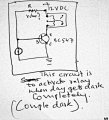
This is my working circuit Picture.
But I dont know what is the calculation to get 180 K.
Thank you all for helping me
 

Attachments

sangpo

Joined Aug 17, 2013
91
I chose 50mA as a typical worst case value for the relay current , as you had not posted which type of relay you are using.
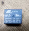
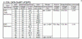
Sir , Since I have no knowledge of electronic, I dont know what type of relay is. I just bought it online for leraning. So that why I have upload the picture relay that we are discussing about, so that you can make it what type of relay is. Thank you
 

ericgibbs

Joined Jan 29, 2010
21,507
OK.
I would us a gain of 20 for a BC547, so if the relay requires 30mA, the Base current should be 30mA/20 = 1.5mA.
So from a 12V supply, allow a 0.7V voltage drop from Base to Emitter of the transistor.
12v-0.7v = 11.3v ....
Rbase = 11.3v/1.5mA = 7500R.

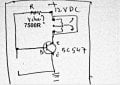
These calculations are for this version of your circuit.
Please post details of the LDR so that we can complete the circuit.

This graph shows a typical LDR response.
AA1 25-Jan-19 10.23.gif

EDIT:

Look at this link.
http://www.technologystudent.com/elec1/ldr1.htm
 

Attachments

Last edited:

MisterBill2

Joined Jan 23, 2018
27,869
Great that it is functioning as desired. And now you are more aware of the other information required for the creation of even a simple design, so the education is of some real value here. It is always important to know all of the performance requirements when creating a design, and it is always important to understand the components used in the design.
So good luck with learning!
 
Top