How to drive Infrared LED off PIC

Thread Starter

JDR04

Joined May 5, 2011
367
OK, I have bought a ZVN4310A mosfet to help drive my IR LED and have attached the mosfets datasheet.

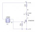
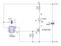
The second atatchment is my schematic.

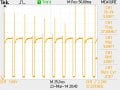
The third attachment shows the wave at point C on my schematic. Its the third schematic that I cannot figure out. The FREQUENCY changes from 38Khz to round 37.3Khz and the DUTY CYCLE becomes erratic, anything from .778 to 77.8 percent.

Should the FREQUENCY and DUTY CYCLE at point C stay at 38Khz and 20% DUTY CYCLE as the PIC is programmed to do? I checked the output at PIN 5 of the PIC and it seems OK.

Really need your guys help on this one.........thanks a lot.
 

Attachments

THE_RB

Joined Feb 11, 2008
5,438
Where's your code?

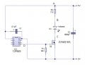
Re the schematic and waveform, you really need to put a 0.1uF cap directly across the PIC power pins. And with a pulsed load current of 650mA I would suggest a 1000uF cap across the main power pins, 5v and gnd.

Re the reason you are getting 37.3kHz instead of 38, I cannot say. It might be your code making 37.3kHz. Or it might be a measuring artifact of your 'scope.

You could try zooming in H axis on the 'scope, from 25uS setting to 5uS or so. Then you should be able to see if the freq (period) is fully stable, or is glitching, and the zoomed in resolution should be enough for you to count gridlines manually and see the actual waveform period in uS, (which you can invert to get the freq).
:)
 

Thread Starter

JDR04

Joined May 5, 2011
367
Hi The RB, thanks for the suggestions.

I have placed the capacitors as you suggested and it seems to have helped a lot.

The code is done with FLOWCODE which is a drag and drop type of programming.

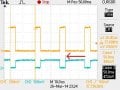
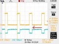
I checked the signal right at the output pin and it seems stable enough. Have attached a screen grab from my scope.(Tektronix 2012C) The top waveform is the output from the microcontroller and the bottom(blue) waveform is taken from point C of my schematic.

Could you tell me if the frequency has to be spot on 38Khz or can there be some sort of tolerence?

Thanks again - JDR04
 

Attachments

THE_RB

Joined Feb 11, 2008
5,438
If you plan to use a standard 3pin IR sensor, they are tolerant of a couple kHz either side of their sweet spot.

You can download the datasheet for your sensor and it should contain info on the frequency tolerance.

I have never used Flowcode but like most beginner friendly languages etc it is unlikely to produce perfect delay times or perfect output frequencies (like you can achieve with carefully coded ASM or C systems). However you can still adjust the period etc in Flowcode to "tweak" the output frequency.
:)
 

Thread Starter

JDR04

Joined May 5, 2011
367
Thanks for that. I'll have a play around with FLOWCODE and see what happens.

Could somebody tell me why the "on period" for channel 2 seems to be opposite to Channel 1. Although the duty period at D is near enough, the duty period of the IR LED actually being "on" is very different?(At C)

What am I missing here? Really appreciate your guys help on this - JDR04
 

Attachments

THE_RB

Joined Feb 11, 2008
5,438
Because you said in post #41 the top wave is from the microcontroller, which is HIGH to turn the FET on.

The bottom wave is from point C (the FET drain pin) which is LOW when the FET is on (and when the LED is on).

It's all good, that is what the waveforms are supposed to look like.
:)
 

Thread Starter

JDR04

Joined May 5, 2011
367
Many thanks to The RB for his patience and help on this.

Would also like to thank all the others that helped me out, much appreciated.

JDR04
 
Top