Facebook
 Google
 GitHub
 Linkedin
OK, I have bought a ZVN4310A mosfet to help drive my IR LED and have attached the mosfets datasheet.
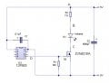
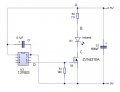
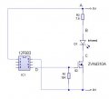
The second atatchment is my schematic.
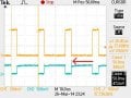
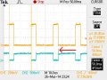
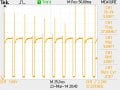
The third attachment shows the wave at point C on my schematic. Its the third schematic that I cannot figure out. The FREQUENCY changes from 38Khz to round 37.3Khz and the DUTY CYCLE becomes erratic, anything from .778 to 77.8 percent.
Should the FREQUENCY and DUTY CYCLE at point C stay at 38Khz and 20% DUTY CYCLE as the PIC is programmed to do? I checked the output at PIN 5 of the PIC and it seems OK.
Really need your guys help on this one.........thanks a lot.
The second atatchment is my schematic.
The third attachment shows the wave at point C on my schematic. Its the third schematic that I cannot figure out. The FREQUENCY changes from 38Khz to round 37.3Khz and the DUTY CYCLE becomes erratic, anything from .778 to 77.8 percent.
Should the FREQUENCY and DUTY CYCLE at point C stay at 38Khz and 20% DUTY CYCLE as the PIC is programmed to do? I checked the output at PIN 5 of the PIC and it seems OK.
Really need your guys help on this one.........thanks a lot.
Attachments
-
55.6 KB Views: 4
-
 10.5 KB Views: 23
 -
 110.7 KB Views: 26