How to determine the inductance of a coil ?

Did you try the time constant method? It can be used to determine an unknown inductance or capacitance provided you have a reliable voltage source and resistor.

For a capacitor, the formula is τ = RC and for an inductor, the formula is τ = L / R

This means at 1τ (2.5us), the voltage at OUT will be ~63% of the supply voltage. At 5τ the voltage will be ~99%. It may seem odd, but it doesn't matter what the supply voltage is so I set mine at 10V for convenience.

My simulation is looking at the rising edge of the square wave but it will also take 1τ (2.5us) for OUT to fall to ~37% of the supply voltage (100-63=37).

For the capacitor using τ = RC:

?s = 1000Ω * 2.5nF = 2.5us

For the inductor using τ = L / R:

?s = 2.5mH / 1000Ω = 2.5us

Therefore, the formula for unknown capacitance is C = τ / R and unknown inductance is L = τ * R. Putting it all together, measure the time it takes for voltage at OUT to reach ~63% of the supply voltage and multiply by R. It's also worth noting both circuits are first order low pass filters.

TC.png
 

MrAl

Joined Jun 17, 2014
13,859
hi Al,
In Dankos circuit he is using the 1meg resistor to give an initial charge to the capacitor ie: 5V, [which takes a little time to fully charge]
then he closes the switch which shorts across the capacitor and the inductor and of course it forms a decaying oscillatory loop.

In my sim I set the capacitor charge IC=5V then I close the discharge switch path.

E
Oh ok that helps to explain it. If I get a chance I'll try that myself. Thanks Eric :)
 

MrAl

Joined Jun 17, 2014
13,859
"Secret" of that physical circuit is in bounceless switch,
which is two crossed freshly stripped copper wires.
Between wires is gap about 1 mm.
I fast an firmly press on cross-point by fingertip and test is done.
Soft tissue of finger effectively damping wires vibration and prevent break of contact.
That's it.
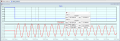
When I use tumbler switch, I have oscillogram with frequency 360.75 kHz (coil self-resonance) instead 7.65 kHz:
View attachment 335866
Hi there,

Thanks for the added information.

When I test the circuit using a bounceless switch though I do not get an oscillatory response. When I do a math analysis, I also do not get an oscillation.

The thing is, are you supplying any energy to the cap or inductor before you open the 'switch' ?

This is interesting because so far there is no good reason for the oscillation, except for what you may be doing which is not explicitly shown of course :)
That's unless I missed something :)
 

ericgibbs

Joined Jan 29, 2010
21,626
The thing is, are you supplying any energy to the cap or inductor before you open the 'switch' ?
Hi Al,.
As I have posted earlier and Danko accepts, he allows sufficient time to charge the Cap from the 5V supply via that 1meg resistor, then he closes the discharge switch.
Which results in a oscillatory discharge response.

E
 

MrAl

Joined Jun 17, 2014
13,859
Hi Al,.
As I have posted earlier and Danko accepts, he allows sufficient time to charge the Cap from the 5V supply via that 1meg resistor, then he closes the discharge switch.
Which results in a oscillatory discharge response.

E
Oh ok great, I'll look into that scenario. Thanks again.
 

ericgibbs

Joined Jan 29, 2010
21,626
hi Al,
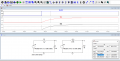
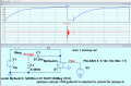
This shows the Cap charge time const, approx 1mSec, so have allowed 5 times that constant to assume fully charged.

The sim plot shows the charge/discharge waveforms, the 2nd image is a time expanded image.
E

Note:
The .IC has been regraded as a Comment, also 10V chosen in order to make Ctau more obvious.

EG57_ 2306.pngEG57_ 2307.png
 

Attachments

Last edited:

MrAl

Joined Jun 17, 2014
13,859
hi Al,
This shows the Cap charge time const, approx 1mSec, so have allowed 5 times that constant to assume fully charged.

The sim plot shows the charge/discharge waveforms, the 2nd image is a time expanded image.
E

Note:
The .IC has been regraded as a Comment, also 10V chosen in order to make Ctau more obvious.

View attachment 335946View attachment 335947
Hi Eric,

Oh, so you have the switch open to start with, then close it after a certain time where the cap is charged up?
 

MrAl

Joined Jun 17, 2014
13,859
Hi Al,
Yes precharge the cap.
E
Hi Eric,

Ok good I'll try that next :)

I am pretty sure this explains it though, because now the series resistance is going to be in the milliohms. Maybe 100mOhms max.
That puts it into the underdamped category which of course means a long ringing oscillation. I think I calculated around 400 Ohms max for this kind of behavior, and 0.100 Ohms sure is a lot less than that, so that explains it then :)

The lower the series resistance, the longer the ringing lasts. We can probably calculate the equivalent series resistance if we get a measurement on the time the ringing starts to the time it gets very close to zero. If it never damps out, then the resistance is zero.
 
Top