How to change gear speed on a multi-planetary gear system based on electricty request?

shortbus

Joined Sep 30, 2009
10,049
t would be based on a water wheel, to which I'd connect a multi-planetary gear system, to which I'd connect a rod magnet.
Maybe your first step in this is to understand how magnets and wire coils work to make electricity. A "rod" magnet rotating in a coil won't do it.

I'd found out that when you begin to extract electricity it creates a sort of resistance, and it lowers the RPM of the magnet/water wheel.
Again learn first. What your talking about is called, BEMF - back electro motive force.
 

Thread Starter

humptydumptyaac

Joined Nov 3, 2021
36
Maybe your first step in this is to understand how magnets and wire coils work to make electricity. A "rod" magnet rotating in a coil won't do it.


Again learn first. What your talking about is called, BEMF - back electro motive force.
Thank you,

Can you clarify further about the cylindrical, rod magnet? I was thinking of using one that is magnetized diametrically, so that as it turns it switches polarity - would that still not work, or were you referring only to magnets magnetized on each end?
 

Reloadron

Joined Jan 15, 2015
7,893
For example, let's say the generator is capable of supplying 10 outlets at 220V AC, with about 2000W each, or 20,000W total.

Well, I'd want to find out, in case I use all 10 outlets at once, powering 20,000W of appliances - how much resistance would be created, and what force/water pressure would need to be applied to the water wheel to prevent it from stopping?
A 20 KW generator is indeed a large generator. I have not seen frequency mentioned? Figure it this way, allowing for loss I have an old 4.0 KW generator in the garage. It uses an 8.0 HP engine under a full load. My whole house generator is 20KW 240 VAC 60 Hz. That is powered by a 35 HP V-Twin engine running on Natural Gas. A water wheel to produce 20 KW is going to be a very large water wheel and need to deliver plenty of HP. Additionally to maintain a line frequency of 50 or 60 Hz. The frequency is a function of the number of poles in the generator and rotational speed.

The two factors are related as per the following formula – Generator Frequency (f) = Number of revolutions per minute of the engine (N) * Number of magnetic poles (P) / 120 Conversely, P = 120*f/N so with that in mind a 2 pole generator rotating at 3600 RPM will produce 60 Hz. The same generator running at 3000 RPM will produce 50 Hz. A 4 pole generator running at 1800 RPM will produce 60 Hz and at 1500 RPM we get 50 Hz.

Years ago working some with aircraft generators we refered to a CSD (Constant Speed Drive) to maintain constant speed for generator RPM.

Anyway you will need one heck of a lot of power to develop 20,000 watts. Another option is to generate DC and drive an inverter and a 20 KW TSW (True Sine Wave) inverter is no easy feat.

Ron
 

shortbus

Joined Sep 30, 2009
10,049
Can you clarify further about the cylindrical, rod magnet? I was thinking of using one that is magnetized diametrically, so that as it turns it switches polarity - would that still not work,
Again you show little knowledge of electrical generation. I'm not saying they don't make a rod magnet like you want but have never seen one. I know of no generator that only uses a single magnet with 2 poles, it's usually many magnets on the rotor, not just one.

Your rod magnet if it exists would have to be very long to make the power your seeming to want. That is why they use several magnets, to make more electricity and to make the generator in a smaller package.

You evidently have Google or some other search engine since you found this forum. Why not use the search to find out more about how and why they do things to get a generator to work. While your looking also try to see why and how they regulate the voltage as it gets generated. Things aren't really as simple as you seem to think.
 

Zod

Joined Jul 3, 2011
13
You would have to use power to pump it up higher to add potential energy, inevitably at a loss, so...
If there is sufficient drop, a hill ram would be a powerless option to move water to a height. Flow would be the issue, but it would work for short duration/higher power.
 

BobTPH

Joined Jun 5, 2013
11,573
Some stats, Hoover dam:

590 ft head
3,000,000 gallons per second flow capacity
2000 MW generator capacity.

Now that’s a waterwheel!

Bob
 

Ya’akov

Joined Jan 27, 2019
10,262
If there is sufficient drop, a hill ram would be a powerless option to move water to a height. Flow would be the issue, but it would work for short duration/higher power.
A ramp pump trades off momentum of a larger amount of water for lifting a smaller amount higher. In this case, it wouldn't do anything useful. You can't get more out than you put in. The most kinetic energy that can be delivered to the wheel is all of the falling water from its original height. Lifting a smaller amount higher would only be a loss, not an increase.
 

Reloadron

Joined Jan 15, 2015
7,893
Some stats, Hoover dam:

590 ft head
3,000,000 gallons per second flow capacity
2000 MW generator capacity.

Now that’s a waterwheel!

Bob
That is one impressive power generating facility much like Niagra Falls. Going over Hoover Dam always impressed me the way the power line towers are built into the mountain side.

Ron
 

Reloadron

Joined Jan 15, 2015
7,893
Hopefully by plane rather than boat ?
Better said on the highway that crosses over the top of the dam. Crossing the border of the states of Nevada and Arizona. :) It really has some incredible views and consider it was completed in 1935. Niagara Falls is also pretty nice. Hard to beat hydro-electric power generation. :)

Ron
 

GetDeviceInfo

Joined Jun 7, 2009
2,275
. Hard to beat hydro-electric power generation. :)

Ron
only takes a referendum
Quebec hydro

Im thinking for the OP that there should be a relatively easy formula that should state the potential of their stream as head x flow. Extraction efficiency required may then suggest a method, and its subsequent control. For a waterwheel, to keep a constant speed, typically is a wastegate to shunt water past the wheel.
 
Last edited:

Reloadron

Joined Jan 15, 2015
7,893
only takes a referendum
Quebec hydro

Im thinking for the OP that there should be a relatively easy formula that should state the potential of their stream as head x flow. Extraction efficiency required may then suggest a method, and its subsequent control. For a waterwheel, to keep a constant speed, typically is a wastegate to shunt water past the wheel.
I never would have thought:
A proposal to build a new transmission line through Maine to bring Quebec’s hydroelectricity into the northeastern U.S. finally gave environmentalists and fossil fuel companies something they could agree on: opposition to the project.
When environmentalist and fossil fuel companies agree on or oppose something you know it has to be good for the rest of us.

No clue of what's up with the thread starter but they will need a whole lot of horsepower to get 20 KW from falling water. :)

Ron
 

Irving

Joined Jan 30, 2016
5,191
So you have large head/low flow (Turgo) or low head/high flow (Kaplan) type turbines (Kaplan type is more like a wind turbine/propeller in style, better for deep fast-flowing river)

As always the devil is in the detail... Not sure I'd trust that '10 or 20kW' without a lot more info and the price is ridiculously low

Here's another supplier, with more realistic detail in their info but 'price on application'

https://www.micro-hydro-power.com/Micro-Hydro-Turbine-Power-Dual-Nozzle-XJ30-20SCTF4_6-Z.htm

so you are looking at a unit needing a 35m head of water at 100litres/sec flow rate , a 300mm dia feed pipe, giving a 20kW 3-phase output which, together with the control unit, weighs 380kg.

The shipping costs for that alone will be several $100...
 

Thread Starter

humptydumptyaac

Joined Nov 3, 2021
36
I never would have thought:


When environmentalist and fossil fuel companies agree on or oppose something you know it has to be good for the rest of us.

No clue of what's up with the thread starter but they will need a whole lot of horsepower to get 20 KW from falling water. :)

Ron
I am curious about one thing though in regards to the water wheel size.

Can the same result (horse power or watt power) be obtained from a "thicker" water wheel, instead of one larger in diameter?

For example: 1.5 meters in diameter, 2 meters in length, and 50 centimeters in depth of the paddles.

Assuming 30 paddles on the water wheel, then each paddle space would fit about 130 litres of water (if my calculations are correct, even if not accurate - one paddle would still fit quite the amount of water) And assuming the water wheel is encased so that water can not escape to the sides or even to the bottm, until it reaches one third of the way down, then we would have 10 paddles filled with water, or 1300 litres of total water acting down on the wheel.

Assuming 1 litre of mass can produce 9.8 watts theoretically, this would give us about 12.5 kW theoretical, or maybe about 8-9 kW more realistically (not sure)

And assuming we can manipulate the amount of water that can fall onto the water wheel, is that possible?

tl;dr - as a solution to a large diameter, if the water wheel has a smaller diameter, but can fit a great deal of water - would that work to convert meaningful electricity?

I'm attaching a picture as an example of approx. looks.: https://prnt.sc/1z66zbu

Thank you

Screenshot_924.png
 

Irving

Joined Jan 30, 2016
5,191
A wider wheel accommodates more water therefore a higher flow rate (litres/min) but only if there is more flow to be had. Making it wider without increasing the flow rate has no benefit!

Remember

Pout = g x F x D x eff

where
g = 9.81 gravitational constant
F = water flow in litres/sec
D = diameter of wheel in metres
eff = efficiency of wheel, approx 0.85 for a steel one, 0.7 for a wooden one

You can only increase F or D. Making it wider without increasing F actually reduces efficiency!
 

BobTPH

Joined Jun 5, 2013
11,573
I am curious about one thing though in regards to the water wheel size.

Can the same result (horse power or watt power) be obtained from a "thicker" water wheel, instead of one larger in diameter?

For example: 1.5 meters in diameter, 2 meters in length, and 50 centimeters in depth of the paddles.

Assuming 30 paddles on the water wheel, then each paddle space would fit about 130 litres of water (if my calculations are correct, even if not accurate - one paddle would still fit quite the amount of water) And assuming the water wheel is encased so that water can not escape to the sides or even to the bottm, until it reaches one third of the way down, then we would have 10 paddles filled with water, or 1300 litres of total water acting down on the wheel.

Assuming 1 litre of mass can produce 9.8 watts theoretically, this would give us about 12.5 kW theoretical, or maybe about 8-9 kW more realistically (not sure)

And assuming we can manipulate the amount of water that can fall onto the water wheel, is that possible?

tl;dr - as a solution to a large diameter, if the water wheel has a smaller diameter, but can fit a great deal of water - would that work to convert meaningful electricity?

I'm attaching a picture as an example of approx. looks.: https://prnt.sc/1z66zbu

Thank you

View attachment 252425
You've been shown how to do the calculation, why don’t you try it.

Bob
 

BobaMosfet

Joined Jul 1, 2009
2,211
Hi, newbie here.

I want to build an electricity generator.

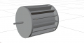
It would be based on a water wheel, to which I'd connect a multi-planetary gear system, to which I'd connect a rod magnet.

I'd found out that when you begin to extract electricity it creates a sort of resistance, and it lowers the RPM of the magnet/water wheel.

I'm trying to find out if there's a way to correlate the amount of wattage extracted to the resistance created, and hopefully estimate how much that would lower the RPM.

For example, if the magnet is spinning at 2000 RPM, with no appliance connected to the generator, then I'd connect an appliance rated at 2000W and begin using it - what resistance would that create, and what would be the RPM of the magnet?

I understand that as a newbie I may ask stupid or incomplete questions, but help me out here please;

For slightly more context: I'm ultimately trying to find out what force would need to be applied on the water wheel, so that when extracting electricty it would keep spinning despite the resistance created.

For example, let's say the generator is capable of supplying 10 outlets at 220V AC, with about 2000W each, or 20,000W total.

Well, I'd want to find out, in case I use all 10 outlets at once, powering 20,000W of appliances - how much resistance would be created, and what force/water pressure would need to be applied to the water wheel to prevent it from stopping?

Now this may be 2 questions in 1, I only provided the second one as bit of context.

Mainly I'd want to know how to calculate the resistance created.

Thank you.
Un-newbie yourself over time- here's a good starting place:

Title: Understanding Basic Electronics, 1st Ed.
Publisher: The American Radio Relay League
ISBN: 0-87259-398-3
 
Top