
Hi,
I would be grateful if you could inform me on how to calculate the cut off frequency at the attached circuit.
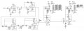
Processing Filter Characteristics 3rd Order LPF + 5th Order HPF
There are four jumpers that may be used to independently control the bandwidth of the analogue signal-processing filters associated with each channel. These filters have two modes of operation:
Mode Low Freq 3dB High Freq 3dB Gain
Low Bandwidth 0.75Hz 11Hz 15 to 77dB (+6dB fixed)
High Bandwidth 0.75Hz 400Hz 15 to 77dB (+6dB fixed)
Normal operation system will utilise the low bandwidth mode. However, there are situations when a faster output signal may be required and it is for this reason that each of the four channels may independently be selected to have a 400Hz bandwidth at the filtered output connector.
Thank you in advance
Panos
I would be grateful if you could inform me on how to calculate the cut off frequency at the attached circuit.
Processing Filter Characteristics 3rd Order LPF + 5th Order HPF
There are four jumpers that may be used to independently control the bandwidth of the analogue signal-processing filters associated with each channel. These filters have two modes of operation:
Mode Low Freq 3dB High Freq 3dB Gain
Low Bandwidth 0.75Hz 11Hz 15 to 77dB (+6dB fixed)
High Bandwidth 0.75Hz 400Hz 15 to 77dB (+6dB fixed)
Normal operation system will utilise the low bandwidth mode. However, there are situations when a faster output signal may be required and it is for this reason that each of the four channels may independently be selected to have a 400Hz bandwidth at the filtered output connector.
Thank you in advance
Panos
Attachments
-
 85.6 KB Views: 26
Last edited:


