How to build true physical intuition for circuit analysis as a beginner? (Need book recommendations)

Status
Not open for further replies.

BobTPH

Joined Jun 5, 2013
11,677
Can we really speak about a "voltage drop"? There is one single voltage only which does not "drop" to another (smaller) voltage.
It drops from the supply voltage to ground. There is no such thing a voltage at a point! It is always a difference between two points. The voltage “drop” is simply the voltage between the two terminals of the resistor. Think from the point of view of the resistor. The ONLY thing the resistor sees is the difference in voltage between its two terminals, it does not matter how that voltage is created.
 

LvW

Joined Jun 13, 2013
2,060
It drops from the supply voltage to ground.
...................
I really cannot agree to this statement.
My mother tongue is not English - however, as far as I understand, the meaning of "drop" is similar to the term "reduction" (something becomes smaller...it drops a little bit).
Lets shortly discuss the following example, which is a typical case:

A non-ideal voltage source Vo has an internal source resistance Ri.
Wenn we connect a load RL to the source (against ground) the available voltage at the output pin of the source is not Vo because of a certain internal loss Vi=I*Ri. Hence, we have a voltage Vout=(Vo-I*Ri) across RL.
Threfore, we can say (regarding the external available voltage across the load):
* The internal voltage is reduced by the "drop" I*Ri , or
* The voltage Vo is dropped due to a loss caused by I*Ri

But we cannot say that there is a voltage drop of Vout=(I*RL) across RL.
This would be a wrong interpretation of the term "voltage drop".
In case of Ri=0 (ideal source) we have Vo=Vout and there is no voltage reduction (voltage drop) at all.

Do you agree to the above? Something wrong?

Added later:
Two other examples for the usage of this term:
A sudden pressure drop in the pipe indicates a leak“
The gas undergoes a rapid temperature drop“
.
 
Last edited:

nsaspook

Joined Aug 27, 2009
16,529
I really cannot agree to this statement.
My mother tongue is not English - however, as far as I understand, the meaning of "drop" is similar to the term "reduction" (something becomes smaller...it drops a little bit).
Lets shortly discuss the following example, which is a typical case:

A non-ideal voltage source Vo has an internal source resistance Ri.
Wenn we connect a load RL to the source (against ground) the available voltage at the output pin of the source is not Vo because of a certain internal loss Vi=I*Ri. Hence, we have a voltage Vout=(Vo-I*Ri) across RL.
Threfore, we can say:
* The internal voltage is reduced by the "drop" I*Ri , or
* The voltage Vo is dropped due to a loss caused by I*Ri

But we cannot say that there is a voltage drop of Vout=(I*RL) across RL.
In case of Ri=0 (ideal source) we have Vo=Vout and there is no voltage reduction (voltage drop) at all.

Do you agree to the above? Something wrong?
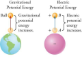
Use the gravity analogy of electrical energy. Height ... Drop...

1794171115369.png
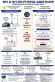
1794171229906.png

Using 'drop' is just a physical math analogy, it's not wrong.
 
Last edited:

MrAl

Joined Jun 17, 2014
13,886
Thank you for your response.
I completely agree to your explanation based on the voltage divider.
Here we have a supply voltage Vo against ground (across the whole circuit) and a smaller voltage Vm (between both resistors) - and a comparison between the two voltages allows us to state that "Vm is smaller than Vo by the voltage drop (Vo-Vm)".
("drop" means "reduction").

However, the explanation as cited above is based on a single resistor only.
Lets assume that we have again a voltage Vo and a resistor connected between Vo and ground.
Can we really speak about a "voltage drop"? There is one single voltage only which does not "drop" to another (smaller) voltage.
And the same applies to your example with two voltage sources against ground (10V and 9v).
Of course, the difference across the resistor is 10-9=1V.
However, makes it sense to say: 10V "drops" by 1V resulting in 9V ? No - the voltage of 9V is externally applied.
We simply have a voltage difference of 1 volt across the resistor - thats all.
Do you see what I mean?

Regards
Hi,

I see what you are getting at, and I can say with confidence that the difference is due to how we interpret the "voltage drop" and that's all.

With the two resistor voltage divider, the top resistor R1 drops some of the supply voltage, but also R2 drops some of the supply voltage. It depends on how you look at it. If you have trouble with R2 dropping voltage, then turn the schematic upside down.

The biggest difference in views though is whether we consider a drop of v=i*R or we consider a drop of v=v1-v2.
If we supply a voltage to the divider we see a drop specified by v=i*R1. If we have a voltage source of 10v and a single resistor of 10 Ohms, the voltage drops from 10v to 0v which makes it hard to say it is not a drop, the only difference is that it is not due to i*R it is due to the difference in two voltages 10v and 0v.

Consider 'calculating' and then 'measuring' the drop across R1 in the divider. The voltage source is (say) 20v and R1=8 and R2=12 Ohms. The current is i=1 amp. Now i*R1=8 volts, and that is a voltage drop, but we could have just measured the voltage at the junction and saw that it was 12v, and then to calculate the voltage drop we would have to say that 20v minus 12v equals 8v, so in that way we got the voltage drop from the difference of two voltages.
We can also put a meter across R1 and we will measure 8 volts. That comes from 20v minus 12v again though because that's what simple voltmeters measure, it is always the difference in voltages between two nodes.

If we had a drop in temperature we would calculate T1-T2. If we had a drop in pressure we would have P1-P2, and in shorter notation often used it would be written as:
P_12 which is "P" with subscript "12", and for the temperatures T_12, and then of course for two voltages V_12. The '1' and the '2' refer to specific terminals and if reversed we write V_21 instead of V_12.
Note in all of these cases we are ONLY talking about ONE quantity with just ONE unit of measure. A difference in anything involves the difference in measurements of one specific thing such as voltage, temperature, pressure, etc.
In a copper rod, the temperature along the rod drops as T1-T2 or with the better notation T_12, and if we measure in reverse it could be T_21. This is certainly a temperature drop and in the same way a wire drops voltage V_12 or V_21.

Notwithstanding all that, you do make a point that should be addressed I believe, just with a slight modification.
We can't say that voltage drops are ONLY due to i*R, but we can say that they often are, and we should point out the difference. In the context of the question I believe he was probably talking about v=i*R drops (or similar) so we can mention the distinction between that and v=v1-v2 which is the more general voltage drop.
So we have at least two ways of describing a voltage drop:
v=i*R, and
v=v1-v2 or
v=v_12 (using subscripts '1' and '2' where '1' is more positive and '2' is the most negative.

If you want to recap that to the starter of this thread that would be fine I think.
 

LvW

Joined Jun 13, 2013
2,060
Hi,

I see what you are getting at, and I can say with confidence that the difference is due to how we interpret the "voltage drop" and that's all.
Yes, agreed. It is a matter of - correct and meaningful (!) - interpretation.

With the two resistor voltage divider, the top resistor R1 drops some of the supply voltage, but also R2 drops some of the supply voltage. It depends on how you look at it. If you have trouble with R2 dropping voltage, then turn the schematic upside down.
Yes, no problem.
For a voltage divider (or any other series connection of elements) it is no problem to measure voltages across the individual parts which are lower than the voltage source feeding the circuit.
Therefore, it makes sense to use the term "voltage drop" - in particular when one of the voltages can be considered as a "load" or a "consumer".

I think, in most - if not in all - cases we are using such a chain of elements because we need a lower voltage (than available from the source) across one of the elements (Examples: (1) LED with series resistor Rs, (2) voltage divider for BJT biasing).
In such a case, the voltage drop across one of the resistors is a wanted/necessary effect (in contast to an unwanted voltage drop across an internal source resistance or along a wire).

The biggest difference in views though is whether we consider a drop of v=i*R or we consider a drop of v=v1-v2.
As I have mentioned above - if the resistor R (with the voltage v=i*R) is (a) part of a series combination of at least two resistors (or any other consumers) and (b) not the load which needs this smaller voltage (compared with the supply voltage) it makes sense to call this "voltage drop".
As far as the difference (v1-v2) is concerned, it depends on the nature of both voltages.
In my view, the term "voltage drop" is appropriate only, when this difference describes the voltage (against ground) which exists across a resistor that is NOT identical to the consumer load.
 

MrChips

Joined Oct 2, 2009
35,299
If this is going off topic, I will keep it brief.

In my opinion, using the term "voltage drop" is poor use of English in describing electrical circuits and we should stop using it. This is particularly important for a beginner trying to understand how circuits behave.
 
Oh WOW!! I am just now seeing this thread, certainly there is a challenge. My thinking starts way before resistors and active components. BUT no math, either.
And certainly not even parts and wires. Just lines and symbols. Battery, switches, and lights! THAT is the way to begin, where the path is understood and the results are simple to imagine. "If there is no path then there is no current", is the first thing one learns. Prior to learning electronic circuits theory is understanding the basic electrical circuit theory. At that time series and parallel become obvious. And not one bit of math involved. Later on power division between loads becomes obvious. And the math follows much later, along with the inclusion of numbers to quantify what is happening.
At that point there are more synbols, and the function of those symbols is more complex, and eventually numbers get involved.
 
Last edited:

dl324

Joined Mar 30, 2015
18,520
The Art of Electronics by Paul Horowitz and Winfield Hill
I am not a fan of that book.

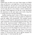
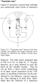
An excerpt:
1794326980192.png
Congenital when referring to non-living things?

1794327044697.png
Two exclamation marks in one paragraph. Then CMOS chips performing "another amusing stunt" of latching up. The authors are certainly easily amused. I don't find latch-up something to be amused about...
 

dl324

Joined Mar 30, 2015
18,520
I agree. It is not a suitable book for beginners.
I don't consider it suitable for anyone.

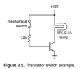
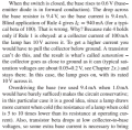
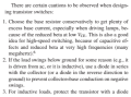
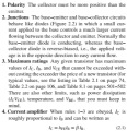
It took 3 revisions before they got transistor saturation sort of right.
1794410323743.png
1794410251859.png1794410273060.png

1794410290920.png
Rules:
1794410708592.png

They mentioned that 1mA of base current would have barely sufficed. I think that's being overly optimistic. And beta also drops with low collector-emitter voltages. And the base-emitter voltage will likely be greater than 0.6V.

They never mentioned using datasheet recommendations (beta of 10 for typical general purpose 2N transistors, e.g. 2N3904, and 20 for some BC transistors, e.g. BC547.

From OnSemi:
1794411066088.png
1794411104884.png
1794411125404.png
 
Last edited:

LvW

Joined Jun 13, 2013
2,060
I don't consider it suitable for anyone.
It is even worse....there is a wrong description/explanation for the state of saturation.
In the quoted part of the text we can read

** "Also, transistor beta drops at low collector-to-base voltages, so some extra base current is necessary to bring a transistor into full saturation."

The mentioned "extra base current " is the RESULT of saturation and is not the rason "to bring a transistor into full saturation"

** "...a small current applied to the base cntrols a much larger current flowing between collector and the emitter."

This is a wrong description of a transistors working principle.
A small current (like the base current ) is never able to "control" a much larger current.
It is always the base-emitter voltage wich controls both - the base and the emitter current.

** "....whereas the base-collector diode is reversed biased"

Wrong!. The state of saturation is defined for a forward-biased base-collector diode (npn case: as a consequence of a voltage Ic*Rc which is large enough to make Vb>Vc (Vbc>0). This condition is the reason for the extra current into the base.
 
Last edited:
The start of this thread was about learning circuit analysis. For me that began at a very early age with battery, buzzer, and light bulb, and button. Then, knowing and understanding what each element of the circuit does, so that the purpose of the circuit could be achieved. The purpose of a switch is to interrupt a current, a battery is to push electricity from + towards -, and the purpose of a light is to light when current passes thru it. That was basic circuit theory as explained to an 8 year old kid. Later I learned that resistors are to develop a voltage across them in proportion to the current passing thru them.
So a big portion of circuit analysis is understanding what the basic elements do. No math yet, not even OHM's Law! Learning what the components did was a major achievement. No math yet, though.

My point is that understanding what the components do is a big part of learning what circuits do.
 
Last edited:

joeyd999

Joined Jun 6, 2011
6,513
The start of this thread was about learning circuit analysis. For me that began at a very early age with battery, buzzer, and light bulb, and button. Then, knowing and understanding what each element of the circuit does, so that the purpose of the circuit could be achieved. The purpose of a switch is to interrupt a current, a battery is to push electricity from + towards -, and the purpose of a light is to light when current passes thru it. That was basic circuit theory as explained to an 8 year old kid. Later I learned that resistors are to develop a voltage across them in proportion to the current passing thru them.
So a big portion of circuit analysis is understanding what the basic elements do. No math yet, not even OHM's Law! Learning what the components did was a major achievement. No math yet, though.

My point is that understanding what the components do is a big part of learning what circuits do.
And that "pushing" a current through a resistor (or across a voltage differential) requires work, and that the work performed is expressed as heat and light (or sound, motion, etc.).
 

panic mode

Joined Oct 10, 2011
5,445
one way to imagine current is movement of crowds/herds/flocks... something one can recall from a real experience.

using humans (as an example of charged particles):
there is a new product (ipod or whatever) and limited numbers are available. store opens at 8AM sharp. hordes of people are at the doors but cannot enter yet.
no people getting in means zero current.
you open one door, and current is non-zero since everyone need to go through same door... that door is one branch that current flows through.
open additional doors and current increases because there are parallel doors and parallel flows.

but maybe that is just entrance(s) to the mall. there may be other obstacles (choke points/resistances) to be overcome (elevators, escalators, stanchions, store doors). those are resistances in series. person that finally reaches the product shelf, had to navigate through all of them. that person was dealing with one resistance after another (series resistance). but for the entire crowd, path to the shelves may be complex circuit to navigate: perhaps 8 parallel doors for mall entrance, then several stairs/escalators/elevators also in parallel with each other, then likely one store door. but those three layers (mall entrances > stairs/ elevators > store door) are in series. and this layered obstacles mean increased resistance (compared to resistance of any single layer).

or use castle as an example... surrounded by rings of obstacles (resistances). could be caltrop fields, temporary barricades or trenches/funnels, moat, outer wall, inner wall, armory. the wider the perimeter (length of moat/walls) the easier is to find weak or not watched spot (therefore low resistance). the more occupied defenders at one spot the lower resistance at other spots...
 
What you need to know in electronics is 4 stuff:The 2 Kirchoffs law , Watts law and the IV equation of every component ur gonna use.If you knew this stuff ,you could build any circuit.
 
Oh WOW!!! Once again: Understanding what components do, then, learning about circuits functioning. There is no substitute for experience, bot your own and the experiences of others.
THAT MEANS LOOKING AT CIRCUITS and understanding how they function, OR, AT LEAST, what they do!
There is not much substitute for a head start! THAT means learning far beyond the formulas! It often includes learning from others.
 
Status
Not open for further replies.
Top