It might help to have a description of what/how it will be used (28volt side), a schematic of what you are connecting to And a nice schematic for the 5 volt source.
Some info on frequency is also helpful and spec for your definition of just how square it must be.
You're assuming the OP has a 28V power supply, which we don't know. Until he answers Gopher's questions, there's nothing more to say that isn't guessing. Maybe Scott has guessed right - we'll see.
Thank you for your mentioned, but the problem is not there, I had attached a new circuit.
Because the npn stage was copied from my another circuit, and i forgot to recheck it.
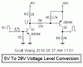
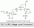
Sure it will. With Q1 saturated there will be about 1mA going through R4 and about 0.7V / 2.7K = .26mA going through R5. That leaves .74mA coming from the base of Q2. That's way more than enough to saturate Q2 with its half mA collector current.
A similar question came up recently - you can use a c_a_s_c_o_d_e (have to do it like that or the spellcheck sneakily changes it to cascade!).
Basically you add a common gate MOSFET with gate to +5V and source to the 5V output, It has current gain of about unity, so if you also need more current as well, add an emitter follower stage.
By now, it starts to look vaguely like the video O/P stage in a CRT monitor - you can use a complementary pair of emitter followers - if crossover distortion might be a problem, put the 2 bias diodes between the CE bases in series between the common base transistor's drain and its drain load resistor.
It might help to have a description of what/how it will be used (28volt side), a schematic of what you are connecting to And a nice schematic for the 5 volt source.
Some info on frequency is also helpful and spec for your definition of just how square it must be.
Yes, it is possible - to a limit. Flip-flops can easily cut frequency by half. Frequency doubling circuits also exist. Using counters you can get many, many options - (you may have to run back through a flip-flop to re square you re-square your wave.
With 5V input voltage and assuming that transistor Q1 2N3904 has Vbe = 0.6V, the current flowing through resistor 1K is 0.6mA and through 4.7K is 1mA. So the base current of Q1 is 1mA - 0.6mA = 0.4mA.
Could you tell me how can I find the beta of Q1 from its datasheet corresponding to that base current?
The datasheet shows DC current gain with different Ic but here I don't know Ic, how can I do that???
With 5V input voltage and assuming that transistor Q1 2N3904 has Vbe = 0.6V, the current flowing through resistor 1K is 0.6mA and through 4.7K is 1mA. So the base current of Q1 is 1mA - 0.6mA = 0.4mA.
Could you tell me how can I find the beta of Q1 from its datasheet corresponding to that base current?
The datasheet shows DC current gain with different Ic but here I don't know Ic, how can I do that???
There are two ways to solve the problem as what you said about the Ib and Ic, the one is to take the 1k Rbe away, and reducing the values of Rb from 4.7k to 4.3k, that is to match the official info of datasheet, when Ib=1mA then the Ic will be equal to 10mA and the Vce will get into the saturation region.
The another way is to reducing the Rb from 4.7k to 2.4k, how did the 2.4k came out, that is :
Rb=(Vin-Vbe1)/(Ib+(Vbe1/Rbe1))
=(5v-0.7v)/(1mA+(0.7v/1k))
=4.3v/0.0017mA
=2.529k, it can use 2.5k or 2.4k.
The official description that the Ib=1mA, Ic=10mA, hfe=10, the Vce will be in saturation, but i like to use it according to my experiment to adjust the values.
The Rb and Rbe will be different, when the Vin and frequency are changing.

 Facebook
 Google
 GitHub
 Linkedin