How this optocoupler module works

Thread Starter

Dadu@

Joined Feb 4, 2022
155
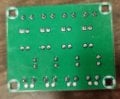
I am having a little trouble understanding the working of the optocoupler module given in this link https://www.electronicscomp.com/pc8...mRYvi6suMKi7edd-tf3GEVsk_VxnCIoIaAoStEALw_wcB

I want to understand that how a micro controller will read the sensor working on 24 volt DC through this module.

I do not see the VCC supply pin at its output terminals. Anyone have any idea how to connect the output terminal of this model to the micro controller?
 

crutschow

Joined Mar 14, 2008
34,285
Likely the output looks like a floating transistor, so you add a load resistor connected to an isolated supply voltage (assuming you want galvanic input to output isolation.

What is the senor signal?
 

MaxHeadRoom

Joined Jul 18, 2013
28,619
Can't see the output side in the picture, the Opto's are Similar to Fairchild FOD817 versions.
It would seem the Board could be used for input or output for a micro.
For input to the micro, you may have to reverse-engineer the board to determine exactly what the components are, look up the 817 and get an idea how it works.
The output of the opto can usually be set up for sink or source.
 

Thread Starter

Dadu@

Joined Feb 4, 2022
155
Try searching for other offers which might have more information: PC817 4 Channel Optocoupler Isolation Module

https://electropeak.com/learn/interfacing-pc817-4-channel-optocoupler-module-with-arduino/

Also EL817 phototransistor photocoupler datasheet: (photo has EL817 on chips, not PC817)
https://www.mouser.com/datasheet/2/143/EVER_S_A0008471837_1-2548735.pdf
If you look at the module in first link, there are four pins in total. I do not understand where is the Vcc terminal that shown in second link figure 7.
 

crutschow

Joined Mar 14, 2008
34,285
There is no Vcc "terminal".
The output looks like a floating transistor, so you add a load resistor connected to an isolated (Vcc) supply voltage (assuming you want galvanic input to output isolation.

What is the sensor signal?
 

MaxHeadRoom

Joined Jul 18, 2013
28,619
When using a dedicated board, you often do not have the option of using the output of the Opto in sink or source mode, i.e., the load resistor/output in the emitter or collector side.
Pins 3&4.
 

BobTPH

Joined Jun 5, 2013
8,813
The description says it has a jumper controlled pull-up or pull-down resistor, but no indication how it is connected.

Bob
 

AlbertHall

Joined Jun 4, 2014
12,345
That board doesn't need a Vcc supply. It is simply 4 optocouplers, each one has an LED on the input, driven as you would normally drive an LED, and an open collector type output.
 

Thread Starter

Dadu@

Joined Feb 4, 2022
155
That board doesn't need a Vcc supply. It is simply 4 optocouplers, each one has an LED on the input, driven as you would normally drive an LED, and an open collector type output.
I didn't understand because Datasheet show that PC817 need vcc supply

Datasheet post #4 figure 7
 

crutschow

Joined Mar 14, 2008
34,285
I didn't understand because Datasheet show that PC817 need vcc supply

Datasheet post #4 figure 7
Below is figure 7 in the data sheet:
The RL load resistor and Vcc are added external to the module.
The resistor could also be placed in series with the emitter to ground with Vcc applied to the collector, to give a non-inverting output.

Why is that difficult to understand?

1653309634967.png
 

MaxHeadRoom

Joined Jul 18, 2013
28,619
In an opto, the input is usually to the anode of the input diode or sink the cathode.?
For the 4pin device you have separate commons for the diode and transistor.
There is only 4 pins on the 817


CPU input for input opto
1653311956944.png
 
Last edited:

Reloadron

Joined Jan 15, 2015
7,501
This is the data sheet for your actual opto-coupler. You have a module board using the opto-coupler. Alone the part would need a series input resistor since the internal LED voltage is typically 1.2 volts and the forward current is 20 mA. The output is Open Collector, all of this is in the data sheet. Now you have a module and looking at it they appear to have a 3.0 Kohm resistor on the input and a 3.0 K ohm resistor on the output. Hard to read the board. The output collector is likely using a 3 K pullup. The Input side also has a LED external as an indicator the module is On. I suggest you give this a read as to interfacing the opto-coupler with an Arduino or similar uC. The link is to the board you have. Also, note what the jumpers on the board are for.

Ron
 

Thread Starter

Dadu@

Joined Feb 4, 2022
155
Why is that difficult to understand?
Let's say we have a sensor which gives 24V DC when activated . We need to read sensor output from microcontroller but micro works only with 5v dc and we are using this four pin opto module between sensor and microcontroller.

I still don't understand what wiring connections are needed between the module and the output of the micro.

Do I have to supply VCC to the mains from the micro controller?

do i have to add an extra resistor separately?

If your answer is yes then where in the module i have to connect the resistor and give 5v vcc supply from micro
 

MaxHeadRoom

Joined Jul 18, 2013
28,619
Post # 14 shows the diagram for input to micro, if opposite logic needed, use the output resistor on the emitter of the Opto and take the input from there.
Do a little "reverse engineering" of the few components on one of the stages and you can determine what is on the board when compared to the #14 DWG.
It states that the output can be switched for pull-up or pull-down.
 
Last edited:

BobTPH

Joined Jun 5, 2013
8,813
Post # 14 shows the diagram for input to micro, if opposite logic needed, use the output resistor on the emitter of the Opto and take the input from there.
Do a little "reverse engineering" of the few components on one of the stages and you can determine what is on the board when compared to the #14 DWG.
It states that the output can be switched for pull-up or pull-down.
Which is puzzling to me because the resistor appears to be connected from one one the opto pins to the output connector. You would need a separate (3rd) connection to use either a pull-up or pull down and a multiple position jumper to select between the two.

Bob
 
Top