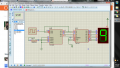
Did you design the circuit you posted or was it given to you by your professor? If he gave it to you, was the instruction given to modify it so it would only count to 8 and then clear to zero?
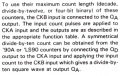
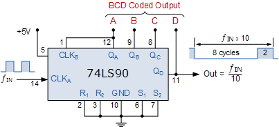
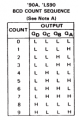
Yes, as stated in the datasheet. This counter will count in BCD mode and in bi-quinary, which will give a divide by 10 square wave (which isn't what you want).
Did you design the circuit you posted or was it given to you by your professor? If he gave it to you, was the instruction given to modify it so it would only count to 8 and then clear to zero?
no... its from me.. i just copied the normal 7-segment that count 0-9. And yes, I was planning to modify it through this one so it would only count to 8 and then clear to zero..
What is the counter doing as wired?
- what counter? the 74ls90?
What were you told to do with unused inputs?
- i connect it on the ground.
What purpose does the 220 ohm resistor serve?
- to resist the power voltage..?
Will the BCD to seven segment decoder work as you have it wired?
- i thought it just connected that way...
The bubbles on the outputs of the decoder indicate the outputs are low active. You have the common terminal on the display connected to ground. Do you think that will work?
What were you taught about current limiting for LEDs?
How would YOU know when the counter got to nine? What device can you think of that could generate a positive signal when it recognized nine?
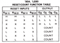
What pin(s) of the 74ls90 could you use to force the count back to zero? If you answer these, you have it made.
I was mistaken. I thought the decoder control signals were tied to ground. That must be your logic supply, but in that orientation it looks like a ground.
What were you taught about limiting LED current? The decoder probably can't damage the display, but the display could damage the decoder by exceeding it's maximum power dissipation.
That's the only counter chip in the circuit...
Why did you leave one of the R0 inputs floating? What logic level is TTL at with a floating input?
Why did you use a resistor for one R0 input, but tie both R9 inputs directly to ground?
What will wiring LT#, RBI#, and BI/RBO# to ground do to the decoder?

 Facebook
 Google
 GitHub
 Linkedin