How is a flyback rectifier reverse biased during primary activation?

Thread Starter

johnyradio

Joined Oct 26, 2012
615
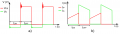
What causes the secondary diode to be reverse biased during tON? Is it to do with the opposing trafo polarity?

During tON, the MOSFET is on and current flows from the input through the primary inductor, linearly charging the coupled inductor and creating a magnetic field around it. In the secondary inductor, the rectifier diode is reverse-biased, which means the transformer is disconnected from the output.

1704391802015.png

https://www.monolithicpower.com/en/primary-side-vs-secondary-side-regulation
 

Attachments

crutschow

Joined Mar 14, 2008
38,324
What causes the secondary diode to be reverse biased during tON?
It's due to the polarity of the input voltage which reverse-biases the output during Ton.
If the diode was forward biased during this time, the transformer would act in the normal mode, transferring current to the output, and the transformer inductance wouldn't store any energy.

The output is generated during the flyback, when the primary transistor goes off.
During flyback, the voltages become reversed and the inductive energy is then transferred to the output through the forward-biased diode.

Make sense?
 

Thread Starter

johnyradio

Joined Oct 26, 2012
615
The induced voltage depends not on the direction if current, but on whether it is increasing or decreasing.
I think this shows that current on the diode is 0 during tON, not increasing current.

1704393516307.png

How does 0 current cause negative voltage?

I think i understand that as current flows between two points then voltage potential between those two points decreases.

But decreasing voltage seems different than negative voltage. I'm still not seeing how we get negative V on the diode.
 
Last edited:

crutschow

Joined Mar 14, 2008
38,324
The input voltage reverses polarity? Isn't Vin a positive DC the whole time?
By input voltage, I meant the voltage across the primary transformer winding.

Vin is constantly positive, but the voltage across the transformer primary winding is not.
When the transistor stops conducting, the stored inductive energy tries to keep the primary current flowing in the same direction.
This generates a positive voltage at the transistor drain, which becomes larger than Vin, and keeps increasing (along with the now positive output voltage) until the output diode starts conducting to transfer the inductive energy to the output.

Make more sense now?
 

BobTPH

Joined Jun 5, 2013
11,465
I think this shows that current on the diode is 0 during tON, not increasing current.

View attachment 311721

How does 0 current cause negative voltage?

I think i understand that as current flows between two points then voltage potential between those two points decreases.

But decreasing voltage seems different than negative voltage. I'm still not seeing how we get negative V on the diode.
It is the change in the primary current that induces a voltage in the secondary.

You need to re-learn how inductance works.

When you place a voltage across an inductor, the current starts increasing at a rate of V / L.

Because the induced voltage in the secondary is negative, the diode prevents any current in the secondary, and the primary acts like a simple inductor.
 

BobTPH

Joined Jun 5, 2013
11,465
I'm still trying to understand the secondary conditions when the transistor is conducting.


Why is it negative?
Because it is wired that way. Reverse the leads in the secondary and it will no longer work.

Edited to add: The circles next to the primary and secondary tell you which leads have the same polarity.
 

crutschow

Joined Mar 14, 2008
38,324
I'm still trying to understand the secondary conditions when the transistor is conducting.
Vin is applied across the dot side of the primary so that applies a negative voltage at the diode, since the dot side of transformer output is connected to ground.

What don't you understand about that?
 

BobTPH

Joined Jun 5, 2013
11,465
My replies started with this post:
The input voltage reverses polarity? Isn't Vin a positive DC the whole time?
And the answer is no. It is not the DC current that causes the induced voltage on the secondary. What changes is the first derivative of the current.
 

Thread Starter

johnyradio

Joined Oct 26, 2012
615
It is not the DC current that causes the induced voltage on the secondary. What changes is the first derivative of the current.
Are you echoing your previous comment?
It is the change in the primary current that induces a voltage in the secondary.
If so, yes, i understand that, and i think it doesn't address my original question.

I'm trying to confirm my hypothesis in my original question, "Why is a flyback rectifier reverse biased during primary activation? Is it to do with the opposing trafo polarity?"

I changed my question to "How?" instead of "Why?", for clarity.

I think your other comment indicates that the answer is yes.
 
Last edited:

joeyd999

Joined Jun 6, 2011
6,204
Completely unrelated, but a fun fact: most of the energy stored in the inductor is stored in the air gap, not in the iron of the core. Therefore, it is important to use properly gapped cores in flyback circuits.
 

Thread Starter

johnyradio

Joined Oct 26, 2012
615
Completely unrelated, but a fun fact: most of the energy stored in the inductor is stored in the air gap, not in the iron of the core. Therefore, it is important to use properly gapped cores in flyback circuits.
aka "coupled inductor", i believe, which is different from a transformer. A transformer doesn't store energy.
 

crutschow

Joined Mar 14, 2008
38,324
Completely unrelated, but a fun fact: most of the energy stored in the inductor is stored in the air gap, not in the iron of the core. Therefore, it is important to use properly gapped cores in flyback circuits.
Don't think that's true.
The air gap is to reduce the permeability of the core, and thus increase the ampere-turns before the inductor saturates.
Since stored inductive energy is proportional the the square of the current then, for example, reducing inductance by two with an air gap, and the ampere-turns by two, increases the stored energy by two.
That is still stored in the inductance of the core, not the air gap.
Otherwise we could just use an air-core inductor without magnetics.
 
Top