 Facebook
 Google
 GitHub
 Linkedin
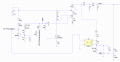
I have a small computer SMPS here in parts, it had bad output caps, it's from 2004, possibly never even used. I'm just using it to study. I have made the entire schematic. I put the Vaux/stby part back together, and I can't get that part to start on it's own, not predictably anyways. A picture of just the parts involved is below., the mosfet is inside the TNY267, below too
Applying 5.12V to the real Vstby rail, is exactly what the TL431 needs to see to turn on right and regulate. (LT1009 in the schem, and ZD1 is a 5v0, LTspice is lacking on zeners.)
However, turning on the PSU, the off-line switcher TNY267, only goes into a low power mode. It generates about 4V for Vaux, and barely more than the diode drop on Vstby.
https://pdf1.alldatasheet.com/datasheet-pdf/view/176833/POWERINT/TNY267.html
I have applied 12V/5V/3.3V to the main rails, and they don't have anyway to create more than about 1.2V on the Vstby rail. I don't see anyway the -5V/-12V rails can affect it either, this layout is pretty basic for a SMPS.
But it did start once or twice, without me applying voltage.
I've tried starting it with a 100 and a 22ohm load, that didn't work. That was only on the Vstby, I haven't tried loading the Vaux, the PWM chip is not turned on, I removed a BJT. I better try that too.
As soon as I apply 5.12V on the rail tho, the opto will allow the TNY to go full power, and then it runs just fine, and is not affected by the other rails at all either.
All of the solder has been replaced or retouched on the PCB, again, I took it down to diodes and resistors, and measured the rest with LCR meter.
Attachments
-
 389.6 KB Views: 24


