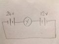
How do we explain powering a load without converting any current?

Status
Not open for further replies.

Thread Starter

Mark Flint

Joined Jun 11, 2017
145
Most electrical signals carried by currents travel at speeds on the order of 108 m/s, a significant fraction of the speed of light. Interestingly, the individual charges that make up the current move much more slowly on average, typically drifting at speeds on the order of 10−4 m/s.
...
The resulting electrical shock wave moves through the system at nearly the speed of light. To be precise, this rapidly moving signal or shock wave is a rapidly propagating change in electric field
Electrical signals (rapidly propagating change in electric field) are carried by currents (electrons). Yet elsewhere it says that electrical signals ARE free charges, ie, electrons. I can't see a clear distinguishing between current, charge, signal or electron. And I thought a change in the electric field was voltage, no?
 

nsaspook

Joined Aug 27, 2009
16,406
Electrical signals (rapidly propagating change in electric field) are carried by currents (electrons). Yet elsewhere it says that electrical signals ARE free charges, ie, electrons. I can't see a clear distinguishing between current, charge, signal or electron. And I thought a change in the electric field was voltage, no?
That 10^8 M/S is the system EM energy transmission speed using conductors with free electrons to guide electrical energy across a dielectric (vacuum, air, a cable insulator).
https://en.wikipedia.org/wiki/Velocity_factor
https://en.wikipedia.org/wiki/Speed_of_electricity
The speed at which energy or signals travel down a cable is actually the speed of the electromagnetic wave traveling along (guided by) the cable. i.e. a cable is a form of a waveguide. The propagation of the wave is affected by the interaction with the material(s) in and surrounding the cable, caused by the presence of electric charge carriers (interacting with the electric field component) and magnetic dipoles (interacting with the magnetic field component). These interactions are typically described using mean field theory by the permeability and the permittivity of the materials involved. The energy/signal usually flows overwhelmingly outside the electric conductor of a cable; the purpose of the conductor is thus not to conduct energy, but to guide the energy-carrying wave.[1]:360
From the current physics link.
Electrical signals are known to move very rapidly. Telephone conversations carried by currents in wires cover large distances without noticeable delays. Lights come on as soon as a switch is flicked.
What it means by that is the actual electron response is a drift speed ~10^−4 m/s to the applied potential vs the signal propagation speed of changes of that potential at near the speed of light as a electric field.
 

crutschow

Joined Mar 14, 2008
38,634
"The energy/signal usually flows overwhelmingly outside the electric conductor of a cable; the purpose of the conductor is thus not to conduct energy, but to guide the energy-carrying wave.[1]:360"

Then why does the resistance of the cable affect the amplitude of the signal at end of the cable?
 

nsaspook

Joined Aug 27, 2009
16,406
"The energy/signal usually flows overwhelmingly outside the electric conductor of a cable; the purpose of the conductor is thus not to conduct energy, but to guide the energy-carrying wave.[1]:360"

Then why does the resistance of the cable affect the amplitude of the signal at end of the cable?
Electrical energy that is converted to KE (thermal heat and vibration energy) in the atoms of the conductor as that electrical energy travels around and down the cable is a loss of electrical energy (signal amplitude at the end of the cable). The directional energy flux/flow is a vector function called the Poynting vector. The resistance of the cable affects the drift speed and the current density of free charges at X applied potential to the conductor. Low current density is usually a good thing unless you want the wire to be a heater with higher resistance.
https://en.wikipedia.org/wiki/Current_density
The current density of free charges is one factor in computing the Poynting vector direction. If the energy flux is parallel to the wire axis, all electrical energy delivered if the dielectric is perfect. If the energy flux tilts into the wire, the energy flow from some part of the electromagnetic field moves into wire producing resistive Joule heating in the wire.

https://www.furryelephant.com/conte...tric-current/surface-charges-poynting-vector/
poynting.png
 
Last edited:

Thread Starter

Mark Flint

Joined Jun 11, 2017
145
What it means by that is the actual electron response is a drift speed ~10^−4 m/s to the applied potential vs the signal propagation speed of changes of that potential at near the speed of light as a electric field.
So what are we measuring in amps, electron drift, signal speed or neither?
 

nsaspook

Joined Aug 27, 2009
16,406
My eyes glaze over when I see all that math.
It's way more than I need to determine the power through a cable.
True, that's why use circuit and transmission line theory instead of field theory. This is the rathole you enter when you need to incorporated the interaction of electrons in circuits in a microscopic electrical energy discussion.

My advice, as usual, is to forget electrons when trying to understand things that can be easily handled by circuit and transmission line theory.
 

Thread Starter

Mark Flint

Joined Jun 11, 2017
145
As you have demonstrated, the current is constant, but the voltage across then bulb is dropped,,

so you have a change in power / or another way joules.


There is nothing more to it than that
Agreed, in the simple circuit I mentioned with the bulb running between the two terminals of a battery there is an obvious voltage drop across the load. But looking at another simple circuit - adding another positive voltage source after the bulb you have a situation where there is no apparent voltage drop across the bulb. This situation seems to say that the voltage drop is not responsible for, or even involved in the delivery of energy.
 

Thread Starter

Mark Flint

Joined Jun 11, 2017
145
The energy reaching the load is equal to that
developed at the battery (assuming there are no losses
in the transmission line). If the load absorbs all of
the energy, the current and voltage will be evenly
distributed along the line.
Thanks for your input. Do you have any thoughts on how the load absorbs energy?
 

nsaspook

Joined Aug 27, 2009
16,406
Agreed, in the simple circuit I mentioned with the bulb running between the two terminals of a battery there is an obvious voltage drop across the load. But looking at another simple circuit - adding another positive voltage source after the bulb you have a situation where there is no apparent voltage drop across the bulb. This situation seems to say that the voltage drop is not responsible for, or even involved in the delivery of energy.
Make a simple schematic of exactly what you mean.
 

BobTPH

Joined Jun 5, 2013
11,606
Agreed, in the simple circuit I mentioned with the bulb running between the two terminals of a battery there is an obvious voltage drop across the load. But looking at another simple circuit - adding another positive voltage source after the bulb you have a situation where there is no apparent voltage drop across the bulb. This situation seems to say that the voltage drop is not responsible for, or even involved in the delivery of energy.
Why would you think there is no voltage drop across the bulb? What you have described is two batteries in series driving a bulb. If the batteries are the same, it will see twice the voltage and twice the voltage drop.

Unless you mean the batteries in the opposite polarity of each other. In this case there is indeed no voltage drop and no current flowing and the bulb does not light.

Bob
 

crutschow

Joined Mar 14, 2008
38,634
adding another positive voltage source after the bulb you have a situation where there is no apparent voltage drop across the bulb.
Au contraire.
You diagram shows a 24V battery being opposed by a 12V battery so there is 12V left which appears across the bulb.
Why do you think there is none?

Incidentally, the 12V battery has current going in its positive terminal and out its negative terminal, so is being charged in that scenario.
 

Delta Prime

Joined Nov 15, 2019
1,311
Thanks for your input. Do you have any thoughts on how the load absorbs energy?
This is as simple as it gets for me, describing the difference in potential illustrated by a DC source(battery),the difference in potential using points of charge (+)(-) as it moves down the transmission line in respect to (battery), direction of travel,the lines of force to represent the electric field that exists between the opposite kinds of charge on the wire(transmission line),the magnetic field created by the electric field
moving down the line.
The moving electric field and the accompanying magnetic fieldconstituting an electromagnetic wave that is moving from the generator (battery, energy) towards the load,reaching the load,which is the resistor. To elaborate on my different point of view, would entail a far more complex circuit. I was unsuccessful in helping you with the most simple circuit I could imagine.
My apologies for causing you any confusion. Good luck to you.
 

Irving

Joined Jan 30, 2016
5,195
Incidentally, the 12V battery has current going in its positive terminal and out its negative terminal, so is being charged in that scenario.
More confusingly, though there will still be approximately 12v across the bulb albeit reversed from the original scenario, there may well be far less current flowing than previously, dependant on the 12v battery's technology and state of charge.
 
Status
Not open for further replies.
Top