How do I wire this double blower DC motor with variable speeds?

Thread Starter

Gannz

Joined Apr 30, 2019
11
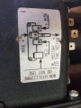
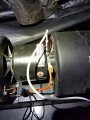
If I put positive to the white lead and negative to the black/orange I get low speed. Does not matter if the pigtail is attached to the left side motor.

If I put negative to the white lead and positive to the black/orange I get high speed. Does not matter if the pigtail is attached.

It seems like I should give the white lead negative and the black/orange positive would give me high, med, or low depending on which post it's attached to on the left side motor but it doesn't matter which lead has +/- and it doesn't matter if the left side motor is even connected. Any ideas?
 

Attachments

Tonyr1084

Joined Sep 24, 2015
7,899
Based on the motor wiring diagram it looks like you apply a positive voltage on either one of the three terminals. I'M GUESSING - - - > but it seems that possibly the body of the motor is supposed to be connected to negative. From what you describe, you hook the motor one way and you get low speed but when you reverse the polarity you get high. That doesn't make sense to me. If this is a DC motor then reversing the leads should reverse the direction the motor spins. IT IS POSSIBLE (not shouting; caps for emphasis) that if it's a blower, when you run it backwards it runs faster because the impellers are designed for a specific direction of rotation. Spinning contrary to their design may be what's making you think one way is high and the other is low.

Try this just for fun: Find a good electrical connection to the motor housing (metal, preferably the motor) and connect the positive to the LOW speed and see what happens. Then try the MEDIUM, then the HIGH. Like I said, I'm just guessing at this, but I suspect That may be your solution.

[edit] As an afterthought, looking more closely at the picture(s) is that thing with what looks like a plug mounted directly inside the fan itself? If so it could be a resistor network that is supposed to give you the differing speeds. TBH, without more details - it's all guesswork.
 

MaxHeadRoom

Joined Jul 18, 2013
28,686
It looks to me as the arrow represents the incoming +ve power lead, and is connected as follows:
+ve to top term MIN
to 2nd down, HIGH
to 3rd down MED
4 Do Not Connect.
Max.
 

Tonyr1084

Joined Sep 24, 2015
7,899
4 Do Not Connect.
What about the negative connection? Where does that go?

Requesting picture in landscape. Would like to get a better look at that pluggie looking thing on the left blower housing. I bet it's a resistor pack for selecting the blower speed.

Also, it looks like the orange wire is plugged into the black wire. If indications on the motor are saying the plug next to the positive symbol are where the positive lead goes then I'd say the white lead goes there and the black goes where the white wire is currently plugged in. Then the positive (orange) wire gets connected to the resistor pack. Positive power is applied to the resistor pack. Depending on where the orange is plugged in - you should get speed control. But keep in mind, without the unit in hand for close examination and testing, all I can do is guess.
 
Last edited:

MaxHeadRoom

Joined Jul 18, 2013
28,686
It would seem the yellow is the common to and the diag. just shows the speed selection jumper, above the yellow in the photo.
Based on the limited info so far.
Max.
 

Tonyr1084

Joined Sep 24, 2015
7,899
OK, I think I've figured it out:

Negative (where your white wire is) is just plain negative. The orange wire (or yellow as Max suggests) goes to one of the three terminals on the side (the part where I'm requesting more info). Also, positive goes to the center terminal. Under that assumption, the piggyback spade connector plugs into the center lead (marked POSITIVE / HIGH). If you want high speed on the blower you connect to the piggyback. If you desire low or medium you connect the orange jumper wire to the appropriate terminal.

HI ME LO.png
 

Tonyr1084

Joined Sep 24, 2015
7,899
As @Max suggests, you plug the piggyback spade plug into the high (center) terminal. Then you can apply positive power to any of the three terminals for low, medium or high. It's just a resistor pack inside the blower. it's inside the blower to keep it cool. Remember to keep polarity correct. Spinning the motor backwards will not blow air and will not keep the resistors cool.
 

MaxHeadRoom

Joined Jul 18, 2013
28,686
Actually a retake of it seems that the BLK (power) if left connected to the orange is HI if the two are left together on the centre term, if separated and the BLK left on the centre term, then the orange can select one of the other two if desired.
Is this what you mean?
Max.
 

Thread Starter

Gannz

Joined Apr 30, 2019
11
OK, I think I've figured it out:

Negative (where your white wire is) is just plain negative. The orange wire (or yellow as Max suggests) goes to one of the three terminals on the side (the part where I'm requesting more info). Also, positive goes to the center terminal. Under that assumption, the piggyback spade connector plugs into the center lead (marked POSITIVE / HIGH). If you want high speed on the blower you connect to the piggyback. If you desire low or medium you connect the orange jumper wire to the appropriate terminal.

View attachment 179706
I swear that's what I was doing but it didn't work. It's working now.

The only thing I did different was separate the piggyback, hook up the orange lead, then apply + to any terminal. Works as it should. Before, I had black lead already connected to the piggyback and a terminal. Applied power and only got high speed no matter which terminal it was on.

Thanks everyone for all the help!
 

MisterBill2

Joined Jan 23, 2018
18,502
It looks to me like that black thing with the blade terminals is a resistor in the air stream of the blower housing. so you have two sections of unequal resistance and 4 speeds, higher resistor, lower resistor, both in parallel, and direct. Not complex and not polarity sensitive.
 
Top