How do I detect if a component is working if it's circuit is open?

Thread Starter

dan_simpson81

Joined Aug 14, 2020
9
Hi guys,

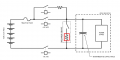
This is my first post here, so sorry if this is in the wrong category. I am currently designing for an electric vehicle and I want to integrate a discharge resistor and relay in parallel to working components (so that the working components are operating normally, but when the relay is activated, these components are shorted and the discharge relay draws the power and discharges the circuit). However, I want to ensure that the resistor is working (since if the component fails during operation, I won't be able to isolate the working components)... How would I go about monitoring the condition of the resistor whilst the relay is closed (aka, whilst the working components are in operation)?

Many thanks for your help in advance!
 

jpanhalt

Joined Jan 18, 2008
11,087
Welcome to AAC, Dan.

A voltage sensor across the resistor will tell whether it is working. Voltage will decrease to baseline (0 V?) . If the resistor is open decrease willbe much slower.
 

Delta Prime

Joined Nov 15, 2019
1,311
I am currently designing for an electric vehicle and I want to integrate a discharge resistor and relay in parallel to working components
Hi there :) could you submit a tiny fraction of the schematic for your electric vehicle involving which circuit you wish to monitor when discharging through the relay.
 

ericgibbs

Joined Jan 29, 2010
18,766
hi dan,
A related question, the answer may help us to understand the problem.

Why is it necessary to know the state/condition of that resistor in a working and non working environment.?

If the resistor did fail what would be the consequences for the rest of the circuit, in a working and non working state.?
E
 
Last edited:

Thread Starter

dan_simpson81

Joined Aug 14, 2020
9
hi dan,
A related question, the answer may help us to understand the problem.

Why is it necessary to know the state/condition of that resistor in a working and non working environment.?

If the resistor did fail what would be the consequences for the rest of the circuit, in a working and non working state.?
E
It's a safety measure; the resistor discharges the circuit in an emergency, therefore ideally I want to be able to monitor it and make sure that in an emergency, the discharge relay will be opened and the discharge resistor will be able to discharge the circuit. It may not be possible, but I thought I would post it up here to see whether any of you guys (which almost definitely have more component knowledge) knew of a way of checking that it is still a working resistor.
 

Thread Starter

dan_simpson81

Joined Aug 14, 2020
9
Just for some clarity, I am looking to, during normal/ non-emergency operation, be able to monitor the resistor (aka, make sure it is not blown, burnt or faulty), so that in the event of an emergency it is definite that it will work...

I haven't heard of resistors doing this before, to my knowledge they are pretty reliable things, but the piece of work I am doing wants me to map out how the vehicle will react if the resistor does fail. Ideally I would like to be able to fit something which would monitor that the resistor is working and then be able to signal this to an on-board computer.

Many thanks for your replies, they are very much appreciated.
 

ericgibbs

Joined Jan 29, 2010
18,766
I want to be able to monitor it and make sure that in an emergency, the discharge relay will be opened and the discharge resistor will be able to discharge the circuit.
Hi,
I am trying to help, so don't misunderstand my replies.

To be sure that the resistor is capable of of carrying the discharge current, in an emergency, it would be necessary to test the resistor with a discharge current.
Just knowing that the resistor is present by passing a low test current etc.. is not good enough.
E

Update:
What is the voltage of the battery pack.?
What is the A-Hr capacity of the pack
What discharge current are you designing for.?
Resistor value and Wattage rating.?
 
Last edited:

kubeek

Joined Sep 20, 2005
5,794
If you need to be absolutely sure that the switch and the resistors are working, then you need to use two swiches, one on top rail and one going to the bottom rail.
That way you can close the top switch and test that it made contact without turning the discharge on, and for example try drawing some test current through the resistor.
Then you can do the same with the bottom switch, and you can do it as a periodical or startup self test, depending on how your device is being operated.
 

WBahn

Joined Mar 31, 2012
29,978
Keep in mind that there are trade-offs involved. The more complicated you make the circuit in order to monitor that the discharge resistor is still good, the greater the chance that something will malfunction at some point.
 

Thread Starter

dan_simpson81

Joined Aug 14, 2020
9
Keep in mind that there are trade-offs involved. The more complicated you make the circuit in order to monitor that the discharge resistor is still good, the greater the chance that something will malfunction at some point.
Exactly, I only ask in order to check that there is no componentry, which I am not aware of, that would be able to report the condition of a resistor such as this. There seems to not be a simple answer... Not to say that any of your help is not appreciated as it has helped me gain a better understanding of what is possible.

As I have said before, as far as I know resistors don't go pop for no reason and I believe a test before the vehicle is activated would suffice.
it would be necessary to test the resistor with a discharge current.
... such as this test, which I can perform by bridging the component with a separate circuit.
 

Thread Starter

dan_simpson81

Joined Aug 14, 2020
9
So just to be sure, when you activate the discharge relay you are disconnecting the power first? Or/ and does activating the discharge relay also deactivate the +Ve air and -Ve air contacts?
Steve G
Correct, the discharge relay is used in order to discharge the intermediate capacitor and powerstage components.
 

djsfantasi

Joined Apr 11, 2010
9,156
Keep in mind that there are trade-offs involved. The more complicated you make the circuit in order to monitor that the discharge resistor is still good, the greater the chance that something will malfunction at some point.
Exactly. What’s monitoring the monitoring circuit? Most of the proposed solutions are less reliable than the resistor. Is the combination sufficiently reliable?
 
Top