How do I connect the wires

Thread Starter

student441

Joined Nov 6, 2021
11
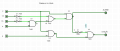
Hello. Its my first year at university and during a class I was able to design an digital circuit but not able to re create it in the breadboard, I dont know which wires connect to who based on the design. Can you help me?

heres the digital circuit Captura de ecrã 2021-11-11 154651.png

and heres what I managed to do with the bredboard/protoboard:

Captura de ecrã 2021-11-11 153821.pngcan you help me understand this?
Your time and attention is deeply appreciated.
Thank You.
 

scorbin1

Joined Dec 24, 2019
103
There are pin numbers next to each pin of the symbols in your schematic. Assuming the symbols in the schematic accurately represent the chips being used, the pin numbers in the schematic should match the chips. However I would verify this with the datasheet just to be sure. It should be as easy as connecting wires between the pins suggested in the schematic. Again I would double check to ensure that the pin numbers of the chips in the schematic match that of the data sheet for each chip. Pin 1 on each chip is denoted by the white dot and the number follows around the chip in a counterclockwise manner.
 

Thread Starter

student441

Joined Nov 6, 2021
11
There are pin numbers next to each pin of the symbols in your schematic. Assuming the symbols in the schematic accurately represent the chips being used, the pin numbers in the schematic should match the chips. However I would verify this with the datasheet just to be sure. It should be as easy as connecting wires between the pins suggested in the schematic. Again I would double check to ensure that the pin numbers of the chips in the schematic match that of the data sheet for each chip. Pin 1 on each chip is denoted by the white dot and the number follows around the chip in a counterclockwise manner.
Captura de ecrã 2021-11-11 160440.pngI assume these are the schematics
 

dl324

Joined Mar 30, 2015
16,845
Welcome to AAC!
I dont know which wires connect to who based on the design.
1636647394756.png
The K switch is connected to U5-5 (U5 pin 5) and U7-9. You can connect both wires to at the switch, or you can connect U5-5 to the switch and connect U7-9 to U5-5.

The simulator outputs indicate logic level. If you use LEDs on your breadboard, you can't connect them to the outputs without current limiting resistors. Also note that if you draw too much current, you could affect the outputs.
 

Thread Starter

student441

Joined Nov 6, 2021
11
There are pin numbers next to each pin of the symbols in your schematic. Assuming the symbols in the schematic accurately represent the chips being used, the pin numbers in the schematic should match the chips. However I would verify this with the datasheet just to be sure. It should be as easy as connecting wires between the pins suggested in the schematic. Again I would double check to ensure that the pin numbers of the chips in the schematic match that of the data sheet for each chip. Pin 1 on each chip is denoted by the white dot and the number follows around the chip in a counterclockwise manner.
So for example: the k wire would connect with and at the 5 entry and 9th entry? did I get it right?
I was also advised(during class) to connect the logic doors between each other first instead to the inputs and outputs, how can i go about doing so
 

dl324

Joined Mar 30, 2015
16,845
I was also advised(during class) to connect the logic doors between each other first instead to the inputs and outputs, how can i go about doing so
Wire placement can be done however it's most convenient.

What is a "logic door"? Gates have inputs and outputs, but I've never heard of them being called doors.
 

scorbin1

Joined Dec 24, 2019
103
So for example: the k wire would connect with and at the 5 entry and 9th entry? did I get it right?
I was also advised(during class) to connect the logic doors between each other first instead to the inputs and outputs, how can i go about doing so
Correct. Where the connections actually physically take place really makes no difference fundamentally. You can connect 5 to K and then 9 to K and the circuit would be identical electrically speaking, likewise you connect two wires to pin 9 and then connect those to K and 5 respectively and it would still be the same circuit. Every point between those three connections is the same point electically speaking so it doesn't matter where the two connect together physically, as long as they connect together with only wire/conductor between them. You could even strip a section in the middle of one of the wires and use that as your junction, that wouldn't be advised, simply because it's messy and not following best practices, but it would still work just the same.

Also as dl324 mentioned, as long as you are wiring this up in an unpowered state, the order of connections should not make a difference. Wiring up in a powered state is NEVER recommended.
 

MrChips

Joined Oct 2, 2009
30,712
Here is an example.

I have connected U1-2 to U2-1 with a light blue jumper.
I have connected U3-4 to U4-2 with an orange wire.

For proper documentation, U1 and U3 should be given the same part designation, i.e. U1 since they are on the same IC package.
U4 should be labelled U2.
U5, U7 and U8 should be labelled U3 as per breadboard layout.

1636649581480.png

breadboard example wiring.jpg
 

dl324

Joined Mar 30, 2015
16,845
heres the circuit down bellow:
That link requires membership. Post a well focused picture of your breadboard.

You schematic doesn't show LEDs. How do you have them connected? As I mentioned earlier, you can't draw much current from the outputs without affecting logic levels.
 

Thread Starter

student441

Joined Nov 6, 2021
11
That link requires membership. Post a well focused picture of your breadboard.

You schematic doesn't show LEDs. How do you have them connected? As I mentioned earlier, you can't draw much current from the outputs without affecting logic levels.
That link requires membership. Post a well focused picture of your breadboard.

You schematic doesn't show LEDs. How do you have them connected? As I mentioned earlier, you can't draw much current from the outputs without affecting logic levels.
I am sorry heres an image down bellow:
implementation bbreadboard.png
Im sorry if it's confusing I tried my best to make it more organised. I used LED's because I don't know how to check i the outputs are working , and thought I just needed to conect them to the pogic gates and the +- PART of the board.
 

dl324

Joined Mar 30, 2015
16,845
Im sorry if it's confusing I tried my best to make it more organised.
It would be easier to read if you didn't cross wires of the same color and used 90 degree angles.
I used LED's because I don't know how to check i the outputs are working , and thought I just needed to conect them to the pogic gates and the +- PART of the board.
As I've already said, you can't put LEDs on outputs without current limiting resistors and you need to make sure that you don't draw enough current from them to change the logic level. This assumes that your breadboard simulator does something reasonable.

You should be able to probe nets with a voltmeter or oscilloscope in your breadboard simulator. Since you also have the circuit in Logisim, you should be able to cross reference nets between the schematic and breadboard to troubleshoot.

Does the circuit work correctly in Logisim?
 

Thread Starter

student441

Joined Nov 6, 2021
11
It would be easier to read if you didn't cross wires of the same color and used 90 degree angles.
As I've already said, you can't put LEDs on outputs without current limiting resistors and you need to make sure that you don't draw enough current from them to change the logic level. This assumes that your breadboard simulator does something reasonable.

You should be able to probe nets with a voltmeter or oscilloscope in your breadboard simulator. Since you also have the circuit in Logisim, you should be able to cross reference nets between the schematic and breadboard to troubleshoot.

Does the circuit work correctly in Logisim?
Yes it does.
 

MrChips

Joined Oct 2, 2009
30,712
Do not connect LED directly to logic output to monitor logic level. The LED will corrupt the voltage.
Use a buffer instead. A current limiting resistor of about 1kΩ should give enough LED brightness.

1636656091381.png
 

Tonyr1084

Joined Sep 24, 2015
7,853
Just trying to be helpful here, but in the future keep this in mind: the 7404 is a Hex Inverter Buffer. It has six inverter buffers on a single chip. In your schematic you use just two of them. That's not a problem. How you identify them correctly would be to indicate U1 as the entire chip. U1A would be just one of the buffers. Next you have a 7408 chip which is a Quad Dual Input AND Gate. That would be U2. U2A would be just one of the buffers. All four of them would be (respectively)U2A, U2B, U2C and U2D. Same would be true of U3, the 7432, Quad Dual Input OR Gate. U3A, U3B and so on. Your schematic looks like it has 8 IC's on it when really, it only has three. Any and all unused gates or buffers should have their inputs held either high or held low, not allowed to float. If they float (no connections) they can oscillate and destroy the chip.

Welcome to a journey of learning and discovery. I enjoyed learning gates and putting them to practical use many years ago. Unfortunately for me I've been away from the hobby for a very long time and what I once knew like my fingernails I now sometimes struggle to put a simple circuit together.
 
Top