 Facebook
 Google
 GitHub
 Linkedin
Morning All,
I need help. I apologize for my severe lack of knowledge. As an engineer I feel I should know how to do this, however, I'm lost. Forgive my ignorance. Here's the problem.
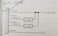
I have three sensors in "NPN Mode". These sensors are fiber optics amps, that trigger when the reflected light is above a certain threshold. Their output wires are shown below. Each sensor has four wires as shown. These are Keyence FS-N43N if that is helpful. In my case, I only need Output 1. Output 2 is not connected.

The measurement equipment we are using is a National Instruments 9232 (3 Channel +/- 30V) card. It's easy enough to use one of the sensors. Power supply +24VDC to power and ground. NI 9232 Channel 1 (-) to sensor wire 4 (black) and NI 9232 Channel 1(+) to Power (+). This results in an on/off signal equal to the input power. I have used a voltage divider circuit to reduce output to ~5VDC to be able to utilize our NI +/-5VDC cards, but this is not necessary for final design.
My problem is when I wire up the second sensor, using the same power supply, a trigger for either sensor results in a trigger of both sensors, by channels 1 and 2 of the NI9232. I'm assuming some sort of isolation is needed between the 2. I have tried different methods of using diodes, resistors to ground, with no luck. I have leaned towards buying an opto-isolated board to run the signal OUT through, but unsure if that would work.
What am I doing wrong? How can I wire three of these sensors, using the same power supply, without cross talk?
Some side notes:
On/Off frequency when in use will be >50kHz at times. If analog circuitry is needed, such that the output signal would be filtered, this low pass filter frequency would need to be very high.
I need help. I apologize for my severe lack of knowledge. As an engineer I feel I should know how to do this, however, I'm lost. Forgive my ignorance. Here's the problem.
I have three sensors in "NPN Mode". These sensors are fiber optics amps, that trigger when the reflected light is above a certain threshold. Their output wires are shown below. Each sensor has four wires as shown. These are Keyence FS-N43N if that is helpful. In my case, I only need Output 1. Output 2 is not connected.
The measurement equipment we are using is a National Instruments 9232 (3 Channel +/- 30V) card. It's easy enough to use one of the sensors. Power supply +24VDC to power and ground. NI 9232 Channel 1 (-) to sensor wire 4 (black) and NI 9232 Channel 1(+) to Power (+). This results in an on/off signal equal to the input power. I have used a voltage divider circuit to reduce output to ~5VDC to be able to utilize our NI +/-5VDC cards, but this is not necessary for final design.
My problem is when I wire up the second sensor, using the same power supply, a trigger for either sensor results in a trigger of both sensors, by channels 1 and 2 of the NI9232. I'm assuming some sort of isolation is needed between the 2. I have tried different methods of using diodes, resistors to ground, with no luck. I have leaned towards buying an opto-isolated board to run the signal OUT through, but unsure if that would work.
What am I doing wrong? How can I wire three of these sensors, using the same power supply, without cross talk?
Some side notes:
On/Off frequency when in use will be >50kHz at times. If analog circuitry is needed, such that the output signal would be filtered, this low pass filter frequency would need to be very high.
Attachments
-
 105.5 KB Views: 9


