And this circuit was advertised by the seller as a toggle on-off switch but to be honest I do not see how it can work this way.
What do you think about this? Can it work?
No. The switch pulls both ff inputs below the CMOS transition level. Vout is forced high while the switch is closed. After the switch is released the output is undetermined.
Here is the classic toggle ff circuit using gates. Any inverting gates will work.
ak
NOTE: the lower 100K resistor should be smaller, like 10K or less.
The circuit posted above works but when pressing the button a second time to set the output low you have to release the switch within about .2 seconds or the output will return to a high state. Changing the 1uf to 4.7uf will give you a full second to release the button making it more practical if using manually.
SG
And here's a variation of the post #2 circuit that requires only one capacitor, and is insensitive to how long the button is held.
It is also ignores contact bounce.
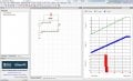
Post 2, except I use a ramp rather than a cap. And of course the gate difference.
I have done the same sim in the past with inverters, same result. It makes sense
as well.
Basically all I and TI ap note trying to explain is when transiting thru threshold region
with some ever present noise if the ramp rate, Trise, too slow lots of transitions occur,
undesired in a logic element. Even with + fdbk. And this does not look at ground bounce
generated noise referred back to gate input effects, more undesired effects.
Over the years I have seen many CMOS gate circuits to implement delay, pulses,
etc.. and always thought long times spend at Vth asking for problems.
True. I have no argument with that.
But the circuits we posted uses a switch to rapidly switch through Vth, not slowly as the voltage source you used.
The zero source resistance eliminates the positive feedback that provides the hysteresis to prevent the oscillations you show.
Add some source resistance and the oscillations will stop.
crutschow, I must be blind as a bat, I see no source R in either post # 2 or # 8 or # 9,
other than cap esr ? Because the caps are acting as the source......or so I think.
What adage did you mention ? You mean this "--The important thing about having knowledge is knowing where it correctly applies.--"
Great adage. I don't have one yet for my posts, I will have to think about that.
Like "Is the earth flat at relativistic speeds ?"
Okay, I see your point, and its low impedance would kill the positive feedback voltage.
But the switch uses that source to rapidly switch the circuit between states, not slowly as in your sim
And 10mV is a lot of noise for such a circuit configuration.
If hysteresis were needed (and I don't think it is for these circuits) you can add a small resistor (e.g 100Ω) in series with the cap in my post #9 circuit.
Yes I should sim switch bounce as well. Then noise becomes the switch bounce
effects piled on top of linear element noise.
Picked the 10 mV just thinking in a CMOS 3 or 5V circuit, switching noise would
generate that. But then it would be instructive to characterize G of gate which I
have not done.
The circuit posted above works but when pressing the button a second time to set the output low you have to release the switch within about .2 seconds or the output will return to a high state. Changing the 1uf to 4.7uf will give you a full second to release the button making it more practical if using manually.
That is solved, as in Wally's circuit, by reducing the lower 100K resistor to something smaller than the other one, like 10% or less (his is 4.7K). It then swamps out the impedance of the R-C timing network, holding the latch in state no matter the voltage of the cap. I updated post #2.
Note - this has *nothing* to do with a slow voltage ramp causing a problem. There is no slow voltage ramp on any CMOS input in this circuit.
View attachment 172063
And this circuit was advertised by the seller as a toggle on-off switch but to be honest I do not see how it can work this way.
What do you think about this? Can it work?
 Facebook
 Google
 GitHub
 Linkedin