How can one solve this circuit?

Thread Starter

antoniu200

Joined Jan 2, 2019
14
Hello!

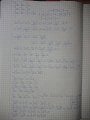
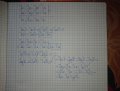
I have a circuit I am asked to find the equivalent resistance of. I have the schematic, but to be able to calculate the equivalent resistance, I have to prove that ICF=IDF=0. I have proven that ICF=IDF, IAC=IAD and ICB=IDB, but I cannot find any relation that would lead me to ICF=0.

I am familiar with Ohm's Law and Kirchhoff's two laws.

Any help is appreciated!DSC_0283.JPG
 

Thread Starter

antoniu200

Joined Jan 2, 2019
14
Wanted to edit, but the time limit had expired.

What I did to get to the relations was write Kirchhoff's second law for the eye A-D-B-F-A. From that, I concluded ICF = IDF. I also wrote Kirchhoff's second law for the eye A-D-F-C-A and deducted that IAC = IAD and, from Kirchhoff's second law for the eye A-D-B-C-A, ICB = IDB.
What might also help is Kirchhoff's first law for the points C, F and D: ICB = IAC - ICF, IFB = IAF + ICF + IDF, respectively IDB = IAD - IDF.
 

AlbertHall

Joined Jun 4, 2014
12,345
Yes, I can see that, hence what I need to do is prove that those 2 resistors do nothing.
Is there any way I can do that?
Picture it without those those two resistors and calculate the voltages at A, F, and B. Thaen you know the current through those resistors and hence their effect on the rest of the circuit.
 

Thread Starter

antoniu200

Joined Jan 2, 2019
14
If I picture the circuit without those nR resistors, I can calculate everything I'd want to know. But I need to find a way to prove those nR resistors do nothing - I can't just eliminate them and say it's fine because it just works.

Please explain as best as you can, since my experience is minimal. I'm not a circuit designer, so I really have no professional experience. I'm just a student trying to get better at direct current circuits.
 

AlbertHall

Joined Jun 4, 2014
12,345
If the voltage across a resistor is zero, then the current through it is also zero. Will zero current affect the rest of the circuit?
 

Thread Starter

antoniu200

Joined Jan 2, 2019
14
If the voltage across a resistor is zero, then the current through it is also zero. Will zero current affect the rest of the circuit?
Of course not. But my question is: where do you get zero from? Why zero? How can I prove it's zero?

You can make a lot of circuits on that U source, by adding or removing resistors from this circuit. But that doesn't necesarily mean that what you add has zero voltage and / or zero current.
 

ronsimpson

Joined Oct 7, 2019
2,988
where do you get zero from? Why zero? How can I prove it's zero?
R=R=R=R
At the top R & R makes a voltage divider so the voltage B-C is half of B-A. For point D the same thing happens. If you put a meter from C to D there will be 0 volts. (Voltage U divided by 2 = voltage U divided by 2)
1614467265067.png
 

Thread Starter

antoniu200

Joined Jan 2, 2019
14
R & R makes a voltage divider so the voltage B-C is half of B-A. For point D the same thing happens. If you put a meter from C to D there will be 0 volts. (Voltage U divided by 2 = voltage U divided by 2)
I have no clue what a voltage divider is. Everything else you said I know and agree with. But doesn't prove that there is no voltage or current flowing through the nR resistors after adding them back.

Why does adding the 2 nR resistors not change anything?
 

Thread Starter

antoniu200

Joined Jan 2, 2019
14
I understand now, thank you! The potential for point C is the same as the potential for point F and D, meaning no voltage will be created on the nR paths.

Thank you for not losing your patience and explaining! I think this method will be useful in the future for solving circuits.
 

AlbertHall

Joined Jun 4, 2014
12,345
You might consider the wheatstone bridge circuit using a galvanometer for the indication.
Why does the galvanometer not disturb the readings?
 

Thread Starter

antoniu200

Joined Jan 2, 2019
14
Well, it's the same situation as here. Every resistor in the Wheatstone bridge has the same voltage, meaning between the 2 connection points of the galvanometer there is no difference in potential, which makes no voltage.
If I come to think about it, this just made me understand Kirchhoff's second law better: it simply reflects differences in potential.

Thank you!
 

MisterBill2

Joined Jan 23, 2018
18,176
Actually, I think that using superposition would be the simple scheme, and the only assumption being that the resistance values "R" are exact. That is a reasonable assumption for a theoretical circuit.
 
Top