How can I properly blend clipping diodes into a circuit smoothly with a potentiometer?

Thread Starter

joulupukki

Joined Sep 9, 2022
279
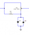
I'm working on a two-stage transistor-based dirt/distortion guitar pedal. I want to have a smoothly blended option for introducing clipping into the sound. This part of the circuit sits between the two transistor stages.

Here are a couple of variations I've tried. The first one sounds great, it's just that the potentiometer doesn't "work" 'til the last little bit of the turn (fully CW). Pretty sure that's because the diodes don't clip 'til the voltage/amplitude of the signal going to them gets large enough.
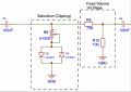
1788880484761.png

With this second one, the behavior of the potentiometer is a little better. The diodes receive a full amplitude from the previous stage and so they clip, but something about it doesn't sound quite right.
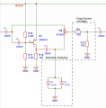
1788879913708.png

Any recommendations/thoughts?
 

schmitt trigger

Joined Jul 12, 2010
2,277
Another question: is your potentiometer linear-taper or log-taper?
Whatever taper you are using, change the pot for the other taper. Same ohmic value.
EDIT, what MrChips is showing is an old trick to make a linear taper behave like a quasi- log tap.
 

Thread Starter

joulupukki

Joined Sep 9, 2022
279
Another question: is your potentiometer linear-taper or log-taper?
Whatever taper you are using, change the pot for the other taper. Same ohmic value.
EDIT, what MrChips is showing is an old trick to make a linear taper behave like a quasi- log tap.
Ah, gotcha. I've tried both 100K linear and 100K log tapers. Not a lot of difference. I did find if I drop to 50K, it didn't quite nix out the clipping to get a clean signal. But, I should probably re-test a number of times.
 

Thread Starter

joulupukki

Joined Sep 9, 2022
279
One other option I've thought of is replacing the blend with a rotary switch that then uses different varieties of diodes with increasing forward voltages with the fully CCW stop being connected to no diodes. I just have to figure out how to make room for that rotary switch in there. I found one from CEDist.com (amplifiedparts) that I've got, but the board it currently placed from the top in an exact spot because I'm using PCB-mounted alpha pots. So I'd have to maybe reshape my PCB to make room. We'll see.
 

crutschow

Joined Mar 14, 2008
38,926
What are the signal levels you want to clip?
What is the DC bias value of the input signal to C6
 
Last edited:

MrChips

Joined Oct 2, 2009
35,280
Thanks! I'll give it a shot this evening. Is your diagram leaving in the unity buffer or replacing that whole section? Can you explain your thinking/reasoning behind why this works and what R1 would do?
The logic behind it is simple.
At the two extreme ends of the pot, you can select 100% clipped or 100% clean. The mid position of a linear pot will give the sum of 50% of the two.

The purpose of R1 is to isolate the clipping from the clean signal otherwise both signals will be clipped. You have to experiment with the value R1.

The input signal must be above the clipping voltage. I suggest starting with 4 V peak-to-peak (i.e 2 V peak amplitude).

Edit: For voltages higher than the clipped signal, you may have to attenuate the clean signal to bring it to the level of the clipped signal.
 

Thread Starter

joulupukki

Joined Sep 9, 2022
279
What are the signal levels you want to clip?
What is the DC bias value of the input signal to C6
I didn't write down the exact signal levels and am going more for the sound/feel of how the clipping happens. I've breadboarded and also built a vero-strip board version of the pedal and using UF4007 diodes seems to clamp down pretty decently (at least the ones I've got).

The DC bias of the 1st transistor's collector is 4.5VDC. I'm using coupling caps in a bunch of places in this circuit to keep DC voltage off any of the potentiometers.
 

Thread Starter

joulupukki

Joined Sep 9, 2022
279
hi joul
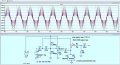
Your 1st post 2nd circuit shows this in LTspice.
Using 5Vppk at 1kHz Sine.
What is your Input voltage amplitude?

E
View attachment 371145
Thanks! I'll have to hook my scope / DMM up to the circuit later to see what my actual input voltage amplitude is. I'm generally playing through a telecaster. It hits the first transistor (high hFE) that I've got biased with a 9VDC-330K and 100K-GND to the base and then a 4.7K-GND on the emitter and a 19K trimmer set to probably 17K to bias at 4.5V.
 

crutschow

Joined Mar 14, 2008
38,926
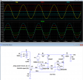
Below is the LTspice sim of a circuit that varies the DC bias on the diodes using a common op amp to change the clip levels.
Does that do what you want?

The 4Vpp input signal has a 4.5V DC bias to emulate the output of your circuit.

The sim shows the clipping for several settings of pot U2 from 0% to 100% of the wiper range.

The diode bias (Clp) range, as determined by the values U2, R3 and R4 (here 0V to ±2V from the +4.5V bias), may have to be changed, depending upon your actual signal levels.

Edit: If you want an asymmetrical clip, you can substitute a 10k pot, connected as a rheostat, for R5.
That will allow the negative clip level to be adjusted to the minimum (0V) up to the setting of the positive clip level.


1788919211493.png
 
Last edited:

Thread Starter

joulupukki

Joined Sep 9, 2022
279
Very interesting circuit crutschow!

Let me explain more about what I'm building...

An older friend passed earlier this year and I discovered he was quite the hoarder, mostly of equipment to multi-track onto tape and convert LPs to cassette. As the clean-up crew was hauling so much stuff out of his basement, I salvaged some 6-lead transistors in TO-5 packages off the floor that they were sweeping up. I wish I could have beat the cleaners to it and salvaged more of them. These transistors are pretty high hFE and have two transistors built into one package. I got about 8 of them where both transistors function.

I thought it would be fitting to use as many components as I could salvage from his stash of components to build a two-stage drive & distortion pedal. It's built off of two chained LPB-1 style circuits and is sounding pretty good (common emitter).

I've been able to avoid using electrolytics in the circuit and instead have a number of NOS tantalum caps from his stash as well. There was a big pile of 4.7nF mica caps in there as well so I found a spot in the circuit where I could use it. It's completely out of place visually, but that's all part of the charm of what I wanted this pedal to be.

The pedal is sounding great. I've got one fully built on a vero-strip board and another on a breadboard. The overdrive sound is pretty close to what my tube amp gives me (though not quite as loose - not a bad thing) and when I engage the clipping diodes, it gives a pretty good distortion sound too.

All that said, at this point I don't want to introduce an opamp into the design and will probably leave it as-is even though the diode blend control isn't the smoothest. I tried a few different variations of that circuit tonight (except for the opamp one) and decided what I had originally works well enough.

For a prototype I've designed and printed a waterslide decal and once the clearcoat dries and I have it mounted I'll post a proper picture of it all.

Thanks for chiming in with some help everyone!
 

MisterBill2

Joined Jan 23, 2018
28,516
I am a bit late into this thread, BUT there is aconcern about those clipping diodes, types UF4007! I have NEVER come across a "UF" diode prefix, but I have used the 1N4007, which is a 1000VOLT(PIV rated) recifier diode. Probably they don't really go into forward conduction sharply at low voltages. Diodes are not all the same! THAT might be a part of the problem where the sound was not quite what you wanted.
 

Thread Starter

joulupukki

Joined Sep 9, 2022
279
I am a bit late into this thread, BUT there is aconcern about those clipping diodes, types UF4007! I have NEVER come across a "UF" diode prefix, but I have used the 1N4007, which is a 1000VOLT(PIV rated) recifier diode. Probably they don't really go into forward conduction sharply at low voltages. Diodes are not all the same! THAT might be a part of the problem where the sound was not quite what you wanted.
The sound is stellar with these diodes. The main issue is that when I expose them enough to the audio path via the potentiometer the volume decreases.
If I understand it correctly the UF4007 is just a faster version of the 1N4007.
 

schmitt trigger

Joined Jul 12, 2010
2,277
No, not exactly. The doping profile of the fast diodes is significantly different, which has shorter carrier lifetimes because it includes dopants that foster carrier recombination.
It has additional side effects, like a higher Vf for a given current density.
 

MisterBill2

Joined Jan 23, 2018
28,516
Consider that diodes across a signal path will certainly clamp the voltage peaks! I think that is the reason for using them!
But diodes are a somewhat complex device, and the current flowing after they go into the conduction mode may continue to flow after the applied voltage drops below the "turn-on" voltage. After all, diodes ARE NON-LINEAR devices. At least, under normal conditions.
 
Top