How can I make an oscillator with 3 capacitors?

ElectricSpidey

Joined Dec 2, 2017
3,342
One of my very first projects as a wee lad was a 6-stage ring oscillator that used different timing of each stage to light a grain of wheat bulb in a backlighted display.

The hard part was the amps for each stage and getting it to power up correctly as in only one stage active.
 

Thread Starter

Electric-Gecko

Joined Dec 10, 2016
56
I have finally bought the components for this circuit and breadboarded it. Well, I breadboarded one variant; this same one posted earlier:


But there were some differences. I removed the 680-ohm resistors and just connected the OR outputs directly to the NOR inputs. Just to make sure it works as an oscillator I had all the comparators share the same voltage on the inverting input. They didn't have any high-speed comparators, so I settled for the LM339N. This should be fine for just testing the basic functionality of the circuit. I thought I already had enough MOSFET's at home, but I could only find two 2N7000 transistors, so I replaced them with the NPN transistors 2N5088. I attached LED's to the OR outputs for visibility.

The circuit didn't work. I wasn't seeing the LED's alternating.

Unfortunately, I don't have an oscilloscope. I haven't managed to find my multimeter, as I've taken a multi-year break from the electronics hobby. This means that I have had no proper way to test voltages or check for loose connections. I don't know if there was something wrong with my breadboard. I might try remaking it with wire wrap, though the non-IC components may still need to be placed on a breadboard.

It's strange that this circuit worked on the Bordodynov's Qspice simulation, but not in real life. Hopefully I will be able to get it right. Of course, Bordodynov's simulation was a little bit different, as the MOSFET gates were connected differently, but I imagine that if that one works than this one should work too.
 

MisterBill2

Joined Jan 23, 2018
27,741
To see the LEDs light you can add a CD4049 and connect the LEDs between the outputs and the V+ line.You can even use two inverters in parallel for twice the LED current. The CD4049 has a much greater sink capability than it's source capability.
 

Bordodynov

Joined May 20, 2015
3,428
I have finally bought the components for this circuit and breadboarded it. Well, I breadboarded one variant; this same one posted earlier:


But there were some differences. I removed the 680-ohm resistors and just connected the OR outputs directly to the NOR inputs. Just to make sure it works as an oscillator I had all the comparators share the same voltage on the inverting input. They didn't have any high-speed comparators, so I settled for the LM339N. This should be fine for just testing the basic functionality of the circuit. I thought I already had enough MOSFET's at home, but I could only find two 2N7000 transistors, so I replaced them with the NPN transistors 2N5088. I attached LED's to the OR outputs for visibility.

The circuit didn't work. I wasn't seeing the LED's alternating.

Unfortunately, I don't have an oscilloscope. I haven't managed to find my multimeter, as I've taken a multi-year break from the electronics hobby. This means that I have had no proper way to test voltages or check for loose connections. I don't know if there was something wrong with my breadboard. I might try remaking it with wire wrap, though the non-IC components may still need to be placed on a breadboard.

It's strange that this circuit worked on the Bordodynov's Qspice simulation, but not in real life. Hopefully I will be able to get it right. Of course, Bordodynov's simulation was a little bit different, as the MOSFET gates were connected differently, but I imagine that if that one works than this one should work too.
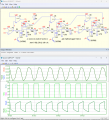
Your scheme didn’t work for me in Qspice, so I fixed it!
 

Bordodynov

Joined May 20, 2015
3,428
That's right, you need to turn on the transistor gate as in a modernized electronic circuit. I tried to run your scheme, but it didn't work out well. Install Qspice for yourself.
 

Attachments

Thread Starter

Electric-Gecko

Joined Dec 10, 2016
56
That's right, you need to turn on the transistor gate as in a modernized electronic circuit. I tried to run your scheme, but it didn't work out well. Install Qspice for yourself.
I have installed Qspice under WINE for Linux. There are some graphical problems, but it's still somewhat usable. Your schematic successfully ran for me.

I noticed that you replaced the comparators with Schmidt triggers. Is this required for it to work? Can I turn my comparator IC into a Schmidt trigger using resistors?

If I changed the transistor gates to other comparator gates it still worked, but it didn't work if I used the OR gate outputs. Do you know why this is? If I did that, it would no longer oscillate, but remain stable with some gate not working as it should.

One strange thing was that it no longer worked as an oscillator if all the reference voltages were set to 20V.
 

Bordodynov

Joined May 20, 2015
3,428
If you read about your chosen comparator in the datasheet, you will see that it has a hysteresis of 4 mV. In this element you can set the hysteresis to 0 (the default value when you do not set the hysteresis is 0).
 

Thread Starter

Electric-Gecko

Joined Dec 10, 2016
56
I have tried breadboarding this circuit again, but this time one step at a time to see what's working. I tried testing the NOR gates and OR gates (74HC02 & 74HC32) on their own, and they seem to work correctly. I then tried connecting them to each-other like the circuit shown but with LED's on the NOR gate outputs and the OR gate B-inputs connected to ground through resistors (instead of the comparator outputs). I then tried connecting connecting these B-inputs to 5 volts, one at a time, and it would toggle between them, as expected. I then set up the comparator with all the bias resistors required for testing, and connected the output to the OR gate B-inputs, disconnecting the resistors to ground. I managed to get it working, where putting a sufficiently high voltage to the noninverting inputs would make one of the NOR gate outputs switch off and a different one switch on.

However, sometimes it would strangely enter a state where multiple NOR gate outputs are turned on at the same time. This should not be possible. I tested and indeed found that the NOR gates were outputting a voltage even when their inputs were at high. I don't have a multimeter on hand, so I don't know if it's the full 5 volts or an intermediate voltage.

I then tried connected the transistors (BJT's, because I don't have enough MOSFETs) the capacitors (bigger ones than shown for better visibility) and resistors (also bigger, for a more visible frequency). Connecting the 5V supply to the other end of these resistors would change which NOR output turned on with a delay, as expected, I then tried connecting the NOR outputs to these resistors to make a loop, and I could sometimes get patterns of one light going on, and then switching to a different light (NOR output) being on.

One strange thing I noticed was that putting 5V on the transistor's (otherwise disconnected) base would result in that LED being turned off, and all the LEDs would be turned off while doing this. I don't see why this would happen.

I didn't manage to get any good results when I finally connected the OR gate outputs to the transistor bases. In this case, all LEDs would be on at a time, but not at full brightness. I don't see how this is happening, as it shouldn't be possible the way this circuit is built.
 

Thread Starter

Electric-Gecko

Joined Dec 10, 2016
56
I found another MOSFET. Using MOSFETs instead of BJTs brings the behaviour closer to expectations. I have continued experimenting to diagnose the problems.

I still have the problem where sometimes multiple NOR outputs are ouputing a positive voltage simultaneously. This often happens with one of the comparators; turning it on results in all 3 NOR gates turning on instead of just one of them. The other NOR gates don't do this. I think there may be a problem where the NOR gate outputs are only half on; outputting an intermediate voltage. I don't yet have a multimeter, so I can only judge with my eyes.

How unusual is it for a NOR gate to be half-on?
 

MisterBill2

Joined Jan 23, 2018
27,741
CMOS logic inputs are very high impedance and not intended to be outside the specified logic levels. So every input must be kept within the correct logic levels for operation according to the specification. THAT MEANS that an open CMOS logic input is going to cause unintended operation every time.
 

Thread Starter

Electric-Gecko

Joined Dec 10, 2016
56
Well, I got that circuit somewhat working. It would oscillate for awhile, but then go back to the state of all-3 NOR outputs being on simultaneously. But then sometimes it would somehow go back. A noisier power supply may have helped.

I finally got around to testing this version of the circuit:

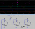
I didn't have any JFETs or depletion-mode MOSFETs, so I used some 3906 PNP transistors. How did it work? It seems to be working perfectly, albeit at a low frequency (which is deliberate) right now. I didn't try this one until just now because I thought the other one was superior, but this turned out to be the much easier way to do it.

I wonder if the reason this one works better is just a matter of the transistors being used. Maybe the one with the comparator would work just as well if I used the same kind of transistor input used in this one. The alternative possibility is that the comparator I'm using just isn't good for this project. Tomorrow I might try a hybrid of the two in which the timing on each is proportional to the reference voltage squared. After some investigation, it turns out that that may be a good timing to use for my power converter circuit.
 

Thread Starter

Electric-Gecko

Joined Dec 10, 2016
56
We still do not know what the purpose of this creation is. And I am still wondering.
Didn't I already link to the other thread where I shared that? Anyway, it's for a special kind of power converter that I am designing. I didn't want to talk about the intended purpose for this on this thread because it would risk derailing the discussion, as it did on that other thread. I started this thread specifically as a fresh start to just talk about the control circuit without it getting clogged with comments telling me that the whole project is silly. It seems that the people who have relevant information to provide are less likely to comment once the thread gets derailed (especially at the beginning), as they think they are behind the discussion.

Feel free to read about it on that other thread, as I shared everything regarding the concept of the whole project, but I consider any discussion on other parts of the project off-topic on this thread.

Anyway, I now own an oscilloscope, and I have tried building multiple versions of the project with mixed success. I will try to share some updates rather soon.
 

Thread Starter

Electric-Gecko

Joined Dec 10, 2016
56
Oh yeah; I forgot to share my progress here. I built an updated version of my circuit on a breadboard, and it works. I tested it with my new oscilloscope.
nor-and-oscillator.png
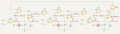
The good thing about this one is that with the added AND gates, the voltages at P1, P2, or P3 can be zero and their phase will be skipped. A comparator switching on because of the voltage dropping to zero won't cause a phase to be skipped. I confirmed that this works with the actual circuit.

It worked well with the 1nF capacitors. When I switched to 120pF capacitors, the timing was quite off. This may be either due to some parasitic capacitance (which I currently don't have a means to measure) or propagation delay on the comparators. It's most likely the latter, as the actual circuit I built used the LM339, which is significantly slower than the MCP6569 shown here.

I wonder if it would be better to swap the comparator inputs and then change the gate arrangement so that the next phase is triggered when a comparator output falls instead of rising. In the MCP6569 datasheet, it appears to have less propagation delay for falling then rising. However, this may not be irrelevant if I switch to a push-pull comparator.

Before building it on a breadboard, I tried doing it wire-wrap, but it didn't work. I don't know why this is, but maybe it's because of some parasitic inductance. My oscilloscope got a different voltage reading on the power pins of the ICs than it did closer to the power supply, even though they were supposedly shorted together.

I have another version I have designed which I was just about to share, but Kicad isn't playing nice right now, so it's not exporting. I will try to show it later, but it's a more complex version that uses a microcontroller, ADCs & DACs so that the duty cycle function can be programmed. I'm also working on one that can optionally take a break between phases when the power supply output voltage goes too high.
 
Top